
Hexfet Switch Circuit

The hexFET (High Electron Mobility Field Effect Transistor) is a type of power transistor that is particularly effective for switching applications in DC circuits. Its ability to handle high voltages and currents makes it suitable for controlling a wide range of devices such as relays, motors, and lamps.
In the described circuit, the hexFET is employed to control the flow of DC power to multiple outputs. The configuration allows for the dynamic switching of resistive loads, represented by R1, R2, and R3, which can be incorporated into or excluded from the circuit as needed. This feature enhances the flexibility of the circuit design, enabling it to adapt to various operational requirements.
The switching action is typically controlled by a gate voltage applied to the hexFET, which allows for rapid transitions between the on and off states. When the gate voltage exceeds a certain threshold, the hexFET enters the conduction state, allowing current to flow through the load. Conversely, when the gate voltage is removed or reduced below the threshold, the hexFET turns off, interrupting the current flow.
This capability is particularly advantageous in applications where load management is crucial, such as in automated systems where different devices need to be activated or deactivated based on specific conditions. The use of resistive loads in the circuit allows for testing and calibration of the switching mechanism, ensuring reliable operation under varying conditions.
Overall, the integration of hexFETs in DC power switching circuits provides an efficient and reliable solution for controlling multiple devices, contributing to the overall performance and functionality of electronic systems. The hexFET can swatch dc power to relays (as shown in A), motors, lamps, and numerous other-devices. That arrangement can even be used to switch resistors in and out of a circuit, as shown in B. Rl, R2, and R3 represent resistive loads that can be switched in and out of the circuit.
Related Circuits
The LM4844 is an integrated audio subsystem designed for stereo cell phone applications. Operating on a 3.3V supply, it combines a stereo speaker amplifier delivering 495mW per channel into an 8Ω load and a stereo OCL headphone amplifier delivering...
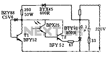
The circuit is designed to activate when the light intensity exceeds 700lx. In this configuration, a phototransistor and the BFY52 transistor are used to trigger the BTY91 thyristor with a current. When light strikes the phototransistor, a positive trigger...
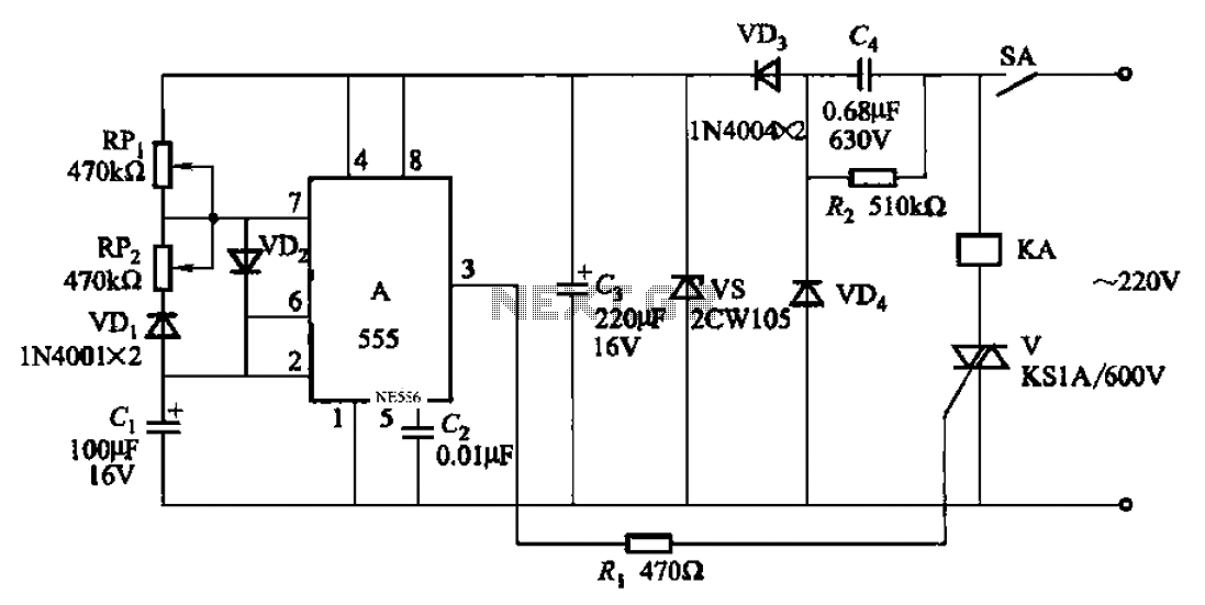
An automatic cycle switch circuit utilizing a 555 integrated circuit (IC) as the control element. It incorporates a capacitive step-down circuit and employs a bidirectional thyristor to control relays or loads with specific on and off timing. The circuit...
A one-inch reed switch with 40 turns effectively activates with the current flowing through a 150-watt lamp (approximately 625 mA), though larger reed switches may necessitate additional turns. If the master appliance draws less current, which is uncommon for...
Very little extra circuitry is needed to do both forward and backward walking sequences along with a few other tricks. The PIC16F818 has a lot of features that work well in this situation. As you can see from the...
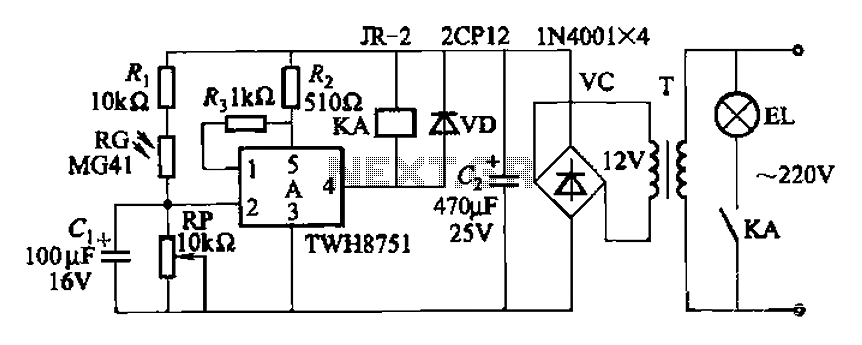
The adjustment potentiometer RP can modify the sensitivity of the device. Capacitors C1 function as an anti-light interference mechanism for instantaneous action. The adjustment potentiometer (RP) is a variable resistor that allows for fine-tuning of the device's sensitivity. By altering...