
Connecting Hall Effect Sensor To BS2

To connect Hall Effect sensors to a BS2 microcontroller for the purpose of counting wheel turns, the following schematic can be utilized. Hall Effect sensors are devices that detect magnetic fields and can be used to sense the position of a rotating wheel.
The schematic should include the following components:
1. **Hall Effect Sensors**: These sensors will be positioned near the wheel to detect the presence of a magnet attached to the wheel. Each sensor will output a digital signal when the magnet passes by, indicating a wheel turn.
2. **Power Supply**: The Hall Effect sensors typically operate at a voltage between 4.5V to 24V. A regulated power supply of 5V can be used to power the sensors, which can be derived from the BS2’s power output if it meets the current requirements.
3. **Microcontroller (BS2)**: The BS2 will be programmed to count the pulses generated by the Hall Effect sensors. Each pulse corresponds to one complete revolution of the wheel.
4. **Resistors**: Pull-up resistors may be needed to ensure that the input pins on the BS2 receive a stable high signal when the sensor is not activated.
5. **Wiring Connections**:
- Connect the Vcc pin of the Hall Effect sensors to the positive terminal of the power supply.
- Connect the ground pin of the sensors to the ground of the BS2.
- Connect the output pin of each Hall Effect sensor to a digital input pin on the BS2.
6. **Programming**: The BS2 will require a program to read the digital inputs from the Hall Effect sensors. Each time a sensor detects the magnetic field, it will send a signal to the BS2, which will increment a counter variable. This variable can be displayed on an LCD or sent to another interface for monitoring.
This setup will allow for accurate counting of wheel turns, providing valuable data for various applications such as speed measurement, distance tracking, or automated systems requiring rotational feedback. Proper calibration and testing should be conducted to ensure reliable performance of the sensors and the microcontroller.I have several Hall Effect sensors and would like to use them with my BS2. One application would be to count wheel turns. I have done a search of the internet but can not find a schematic for connecting it to a BS2. Can anyone help me out with a schematic? I have attached a image of what I want to do. Thanks.. 🔗 External reference
Related Circuits
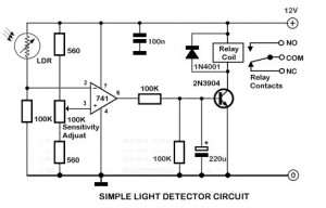
An ambient light sensor circuit is a circuit that utilizes light intensity to perform various applications. An ambient light sensor circuit typically consists of a light-dependent resistor (LDR) or phototransistor that detects the intensity of ambient light. The sensor converts...
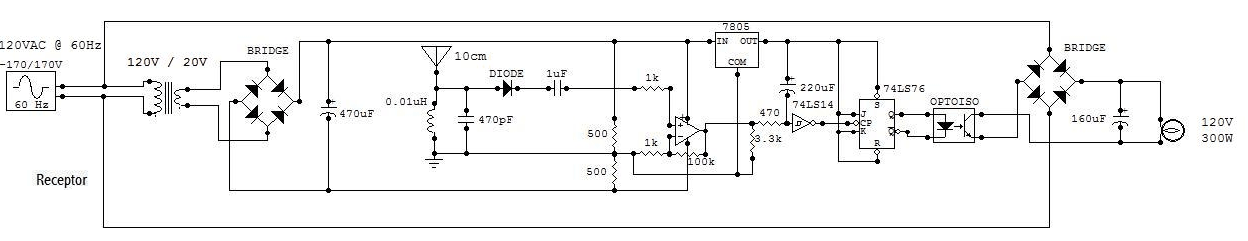
The circuit schematic is straightforward. Information regarding the assembly and testing of circuits is not provided, as there are many instructional resources available. The circuit schematic in question is designed to be simple and user-friendly, allowing for ease of understanding...
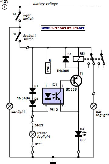
For several years, a rear fog lamp has been mandatory for trailers and caravans to enhance visibility in foggy conditions. When the fog lamp is activated, the fog lamp of the towing vehicle must be turned off to prevent...
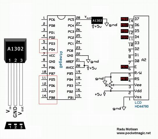
The A1301 and A1302 are continuous-time, ratiometric, linear Hall-effect sensor integrated circuits (ICs). These sensors are designed to provide an accurate voltage output that is proportional to the magnetic field applied. The quiescent output voltage of these devices is...
This circuit is a 73 MHz halogen lamp radio-controlled system. Its purpose is to control the power state of a halogen lamp using a remote control. When the push button on the remote control is pressed, the power state...
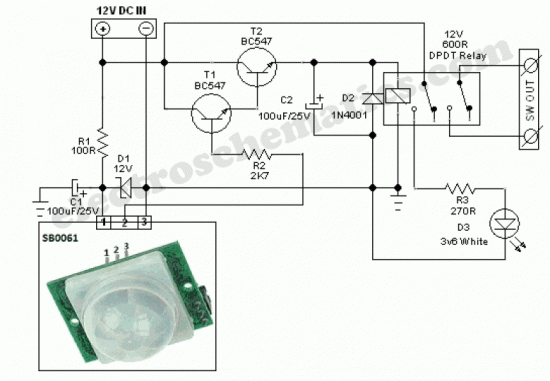
The SB0061 is a pyroelectric sensor module designed for human body detection. It integrates a PIR (Passive Infrared) detector with a Fresnel lens on a compact printed circuit board (PCB), along with an analog integrated circuit (IC) identified as...