
Light Sensor Circuit

An ambient light sensor circuit typically consists of a light-dependent resistor (LDR) or phototransistor that detects the intensity of ambient light. The sensor converts the light intensity into a corresponding electrical signal, which can then be processed by other components in the circuit.
The primary components of this circuit include the light sensor (LDR or phototransistor), a resistor, and an operational amplifier (op-amp) or microcontroller for signal processing. The LDR exhibits a decrease in resistance with an increase in light intensity, allowing it to function effectively in varying lighting conditions. When light falls on the LDR, the resistance decreases, causing an increase in voltage across it, which can be measured and interpreted.
In typical applications, the output from the ambient light sensor can be used to control devices such as automatic lighting systems, where the lights are turned on or off based on the surrounding light levels. This can enhance energy efficiency by ensuring that lights are only active when necessary. Additionally, the circuit can be integrated into smart home systems, allowing for automated adjustments to lighting based on the time of day or occupancy.
For optimal performance, the circuit may include a calibration mechanism to adjust sensitivity levels, ensuring accurate readings in different environments. Furthermore, the use of filtering capacitors can stabilize the output signal and reduce noise, which is particularly important in environments with fluctuating light conditions.
Overall, the ambient light sensor circuit is a versatile and essential component in modern electronic systems, contributing to energy conservation and automation in various applications.Ambient Light Sensor Circuit Light sensor circuit, such as the name is a circuit that utilizes the light intensity / beam for the other applications do. 🔗 External reference
Related Circuits

The circuit depicted in the figure is based on the RF2126, a 2450 MHz end-stage linear power amplifier. The radio frequency (RF) signal enters through input pin 1 and is subsequently amplified by the amplifier stages (pins 5, 6,...
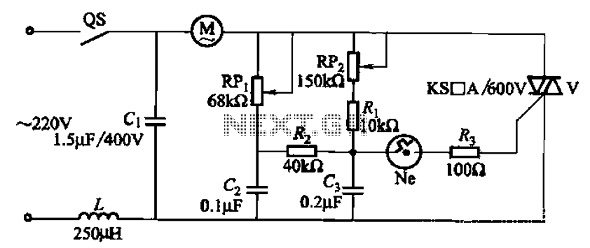
The 3P10 circuit, illustrated in the figure, utilizes a bidirectional thyristor for control. The adjustment potentiometer RPi allows for modification of the minimum motor speed, while the adjustment potentiometer RP2 enables continuous variation of the motor speed, reaching up...
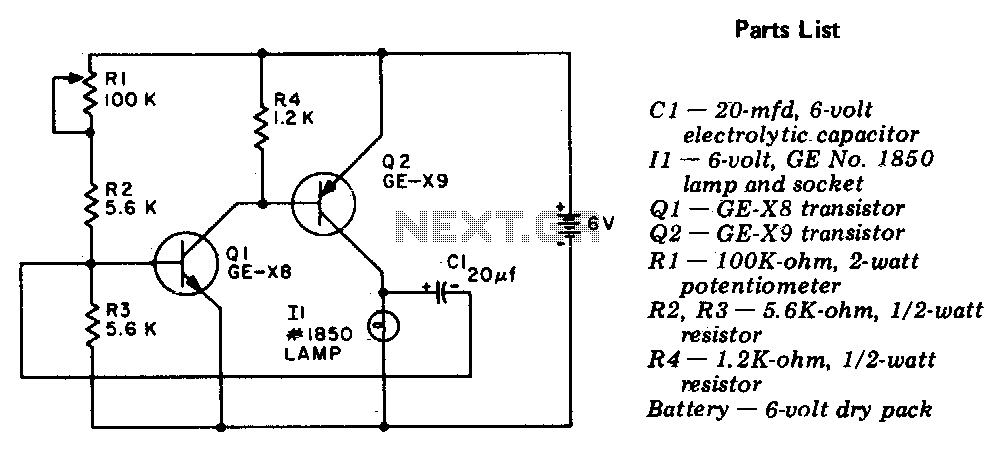
The circuit is a two-stage, direct-coupled transistor amplifier configured as a free-running multivibrator. Both the flash duration and flash interval can be adjusted by turning the potentiometer, R1. The described circuit operates as a two-stage, direct-coupled transistor amplifier, functioning as...

The circuit utilizes a tuned circuit for frequency selection, designed to operate at approximately 51 kHz. The 2N3565 transistor amplifies the output generated by the tuned circuit. The described circuit operates on the principle of resonance, where the tuned circuit...

The thermostat electric circuit operates as depicted in the figure. It has three settings: off, low power (Lo), and high power (Peru HL). When the DIP switch SA is set to the Lo position, 220V AC is directed through...

The circuit of electric blankets is controlled by switch S. When switch S is fully engaged, the entire supply voltage of 220V is applied to the heating wire, resulting in a high-temperature state. When a lower temperature is desired,...