
Turbo Sound effect circuit for your non turbo car

The circuit schematic in question is designed to be simple and user-friendly, allowing for ease of understanding and implementation. This schematic typically includes essential components such as resistors, capacitors, diodes, and transistors, which are arranged to fulfill a specific function, such as amplification, switching, or signal processing.
In a basic circuit schematic, each component is represented by standardized symbols, ensuring clarity and consistency. The connections between these components are indicated by lines, which denote the flow of current. Power sources, such as batteries or power supplies, are usually included to provide the necessary voltage and current for the circuit's operation.
While specific details about assembly and testing are not included, it is crucial to follow best practices when working with electronic circuits. This includes verifying the schematic against the physical layout, ensuring proper component orientation, and utilizing appropriate tools for measuring voltage, current, and resistance during testing.
For individuals seeking to construct or analyze circuits, numerous instructional resources are available online, offering step-by-step guides, video tutorials, and community forums for troubleshooting and advice. These resources can significantly aid in understanding the practical aspects of circuit assembly and testing, complementing the straightforward nature of the schematic itself.The circuit schematic is straightforward, I`ll not try to give information about assembling and testing circuits, there should be lots of instructable.. 🔗 External reference
Related Circuits
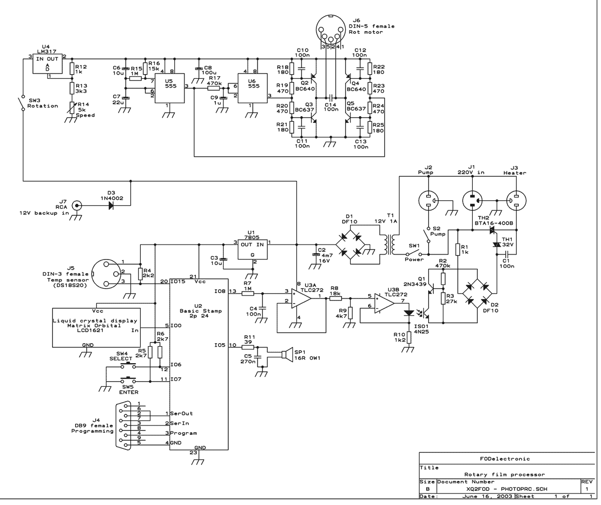
This machine essentially does three things: It controls the process temperature, provides constant agitation of the chemical baths, and performs the timing. The operator must pour in and out the liquids by hand. The heart of the circuit is...
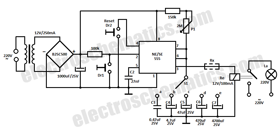
This time delay relay circuit is constructed using the NE/SE555 integrated circuit, manufactured by Intersil, which features a precision timer. The circuit exhibits stability against temperature variations. The NE/SE555 integrated circuit is a versatile timer used in various applications, including...
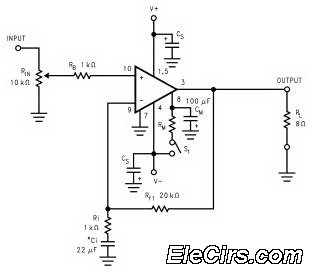
The LM3886 high-performance audio power amplifier circuit schematic is a crucial component in sound reproduction within audio systems. This audio power amplifier utilizes the LM3886 integrated circuit to enhance sound quality and output. The LM3886 is a high-performance audio power...
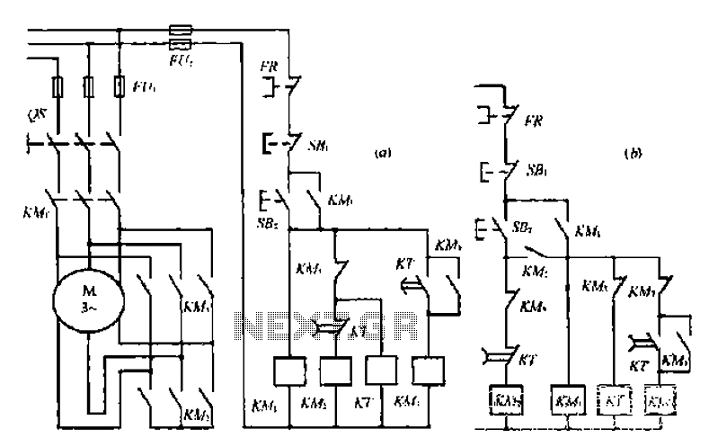
A star-delta switch is utilized for starting circuits, commonly depicted in Figure I-5 (a) of the knife wiring. While this method is effective, it poses security risks. When the motor starts, it can create significant voltage fluctuations that may...
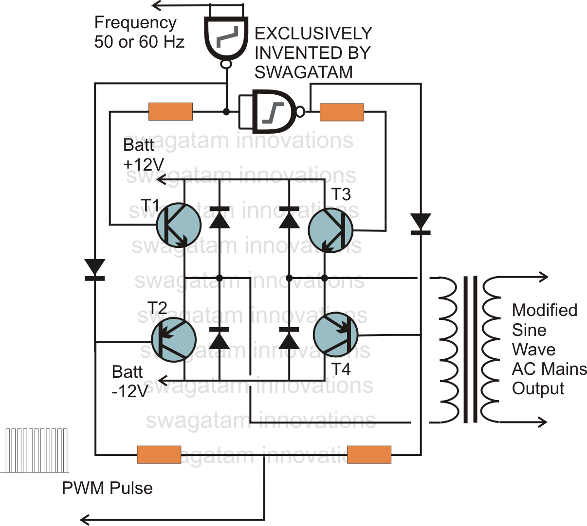
In electronics, an H-bridge circuit refers to a configuration consisting of four individual switching devices, such as transistors or MOSFETs, which can be controlled by external discrete signals from the respective stages of the control circuit. During operation, the...

This 4-channel commutator utilizes the 2N4091 to achieve a low channel ON resistance (approximately 30 ohms) and minimal OFF current leakage. The DM7800 voltage translator is a monolithic device that provides gate drive voltages ranging from 10V to 20V...