
Computer-Controlled 4-20mA Current Loop

The 4-20 mA current loop is a standard method for transmitting analog signals in industrial environments, particularly for process control and instrumentation applications. The current loop operates on the principle of varying current levels to represent different values of a physical measurement, such as temperature, pressure, or flow rate.
In this system, 4 mA typically represents the lowest end of the measurement range, while 20 mA signifies the highest end. This range provides a clear distinction between the minimum and maximum values, allowing for accurate monitoring and control of the equipment. The choice of a 4-20 mA loop is advantageous due to its inherent noise immunity, as the current remains constant regardless of the resistance of the transmission line, thus ensuring reliable signal integrity over long distances.
The current loop consists of a transmitter, which converts the physical measurement into a corresponding current signal, and a receiver, which interprets this signal to control the equipment accordingly. The transmitter may be a sensor or a transducer that is calibrated to output a specific current based on the measured variable. The receiver can be a programmable logic controller (PLC), a digital display, or any other control system capable of processing the current signal.
Powering the loop can be accomplished through a variety of methods, including using a dedicated power supply or a loop-powered device that draws its operating power from the current loop itself. This configuration simplifies installation and reduces the need for additional wiring.
In summary, the computer-controlled 4-20 mA current loop is a robust and reliable method for transmitting analog signals in industrial applications, facilitating effective equipment control and monitoring.In some industries, to control the some equipments they are use computer-controlled 4-20mA current loop. This current loop is used transmit a signal over a.. 🔗 External reference
Related Circuits
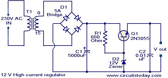
Since my page was first posted, I have received a number of emails asking about a high current power supply. I looked around, but couldn’t find one that was suitable. So, I designed this. It is a linear supply,...
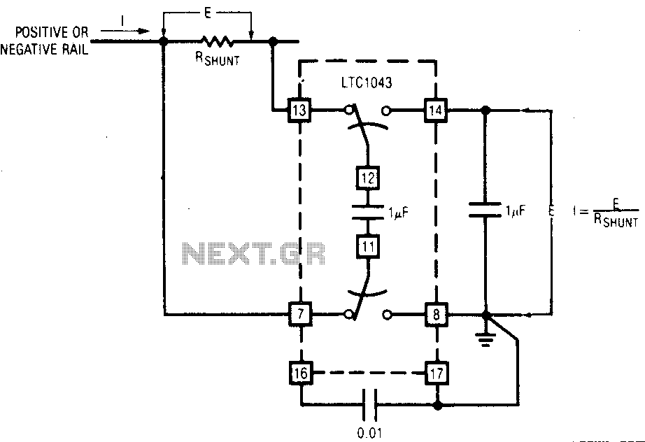
The LTC1043 can be induced through any of its current shunt supply rails. Many cells and solar system applications have this feature. If the reference point is grounded, the voltage output of an unloaded amplifier is minimal, allowing the...
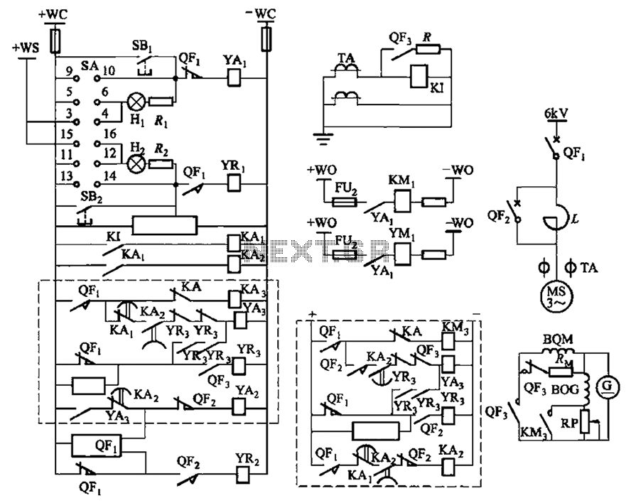
The circuit depicted in Figure 3-189 includes various components such as switch SA, closing button SBi, trip button SBz, de-excitation switch Yaa, and off trip coil YR3. The excitation switch contacts are represented by QF3, which serves as a...
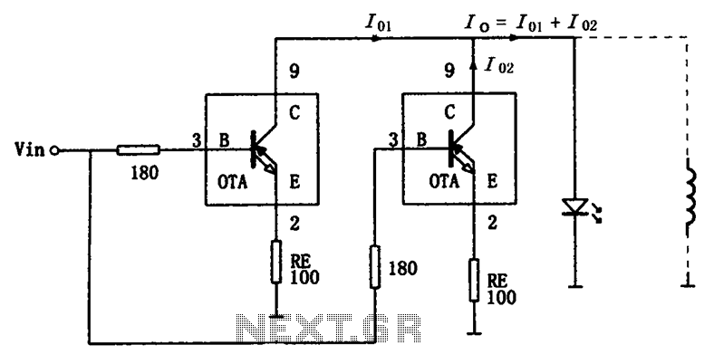
The high-speed parallel current drive circuit utilizes the OPA660 operational transconductance amplifier (OTA). An input signal, Vin, is connected to a 180-ohm resistor equivalent device at the base (pin 3) of the OPA660. The collector (pin 8) is directly...
This voltage regulator circuit can deliver up to 3A at a 12V output voltage. The circuit can be used when a current exceeding 3A is required for regulation. Integrated circuit (IC) regulators with such high current ratings are relatively...
All ATL-3 loop windings are centre tapped and balanced w.r.t. their amplifier/receiver chassis ground, and therefore electric field interference pick up tends to self cancel. Magnetic noise fields, e.g. televisions and the electric meter box, or electromagnetically radiated interferences,...