
Contrast Control for LCDs

The circuit utilizes the LM334 integrated circuit to provide a reliable and efficient constant current source for the LC-Display contrast adjustment. The LM334 is a versatile current source that can maintain a consistent output current with minimal variation due to changes in supply voltage or temperature. The design includes a resistor, R1, which sets the desired output current based on the formula provided. The temperature dependency of the LM334's output current means that careful calibration is required, particularly in environments with significant temperature fluctuations.
In practical applications, the circuit can be implemented by connecting the output of the LM334 to the contrast pin of the LC-Display. The adjustment potentiometer allows for fine-tuning of the current, enabling the user to achieve the optimal contrast level for visibility. As the power supply voltage decreases—common in battery-operated devices—the constant current feature ensures that the display remains legible without the need for manual adjustments.
This design significantly improves energy efficiency, making it suitable for portable devices where battery life is critical. The implementation of this circuit can lead to a reduction in power consumption while maintaining display performance. Users should also conduct preliminary tests when integrating this circuit with newer display technologies to verify that the desired brightness control can be achieved effectively. Overall, this approach to contrast adjustment enhances usability and extends battery life in electronic devices.The adjustment control for the contrast of an LC-Display is typically a 10-k potentiometer. This works fine, provided that the power supply voltage is constant. If this is not the case (for example, with a battery power supply) then the potentiometer has to be repeatedly adjusted. Very awkward, in other words. The circuit described here offers a s olution for this problem. The aforementioned potentiometer is intended to maintain a constant current from the contrast connection (usually pin 3 or Vo) to ground. A popular green display with 2x16 characters supplies` about 200 µA. At a power supply voltage of 5 V there is also an additional current of 500 µA in the potentiometer itself.
Not very energy efficient either. Now there is an IC, the LM334, which, with the aid of one resistor, can be made into a constant current source. The circuit presented here ensures that there is a current of 200 µA to ground, independent of the power supply voltage.
By substituting a 2. 2-k potentiometer for R1, the current can be adjusted as desired. Circuit diagram:The value of R1 can be calculated as follows: R1 = 227x10-6 x T / I. Where T is the temperature in Kelvin and I is the current in ampG¨res. In our case this results in: Note that the current supplied by the LM334 depends on the temperature. This is also true for the current from the display, but it is not strictly necessary to have a linear relationship between these two. Temperature variations of up to 10 ° will not be a problem however. This circuit results in a power saving of over 25% with an LCD that itself draws a current of 1. 2 mA. In a battery powered application this is definitely worth the effort! In addition, the contrast does not need to be adjusted as the battery voltage reduces. When used with LCDs with new technologies such as OLED and PLED it is advisable to carefully test the circuit first to determine if it can be used to adjust the brightness.
The value of R1 can be calculated as follows: R1 = 227x10-6 x T / I. Where T is the temperature in Kelvin and I is the current in ampG¨res. In our case this results in: The current supplied by the LM334 depends on the temperature. This is also true for the current from the display, but it is not strictly necessary to have a linear relationship between these two. Temperature variations of up to 10 ° will not be a problem however. This circuit results in a power saving of over 25% with an LCD that itself draws a current of 1. 2 mA. In a battery powered application this is definitely worth the effort! In addition, the contrast does not need to be adjusted as the battery voltage reduces. When used with LCDs with new technologies such as OLED and PLED it is advisable to carefully test the circuit first to determine if it can be used to adjust the brightness.
🔗 External reference
Related Circuits
Modify it to click and latch a relay when the button is pressed from anywhere in the house. Additionally, if possible, unlatch the relay when pressed again. A flip-flop circuit may be created to take the first signal and...
A circuit designed to extract and measure the modulated carrier signal from an infrared (IR) remote control. This circuit does not physically separate control pulses from modulation; instead, it amplifies the complete received signal, allowing the waveform to be...
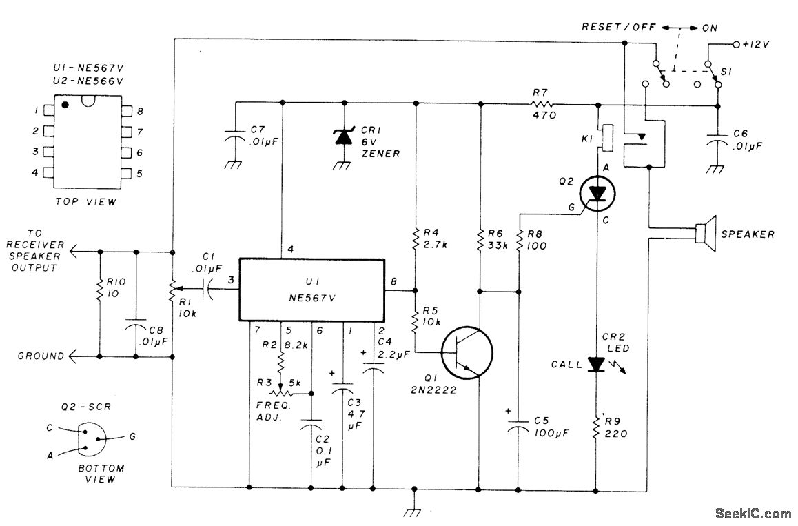
This circuit allows for monitoring a local VHF FM repeater for calls from friends without the need to listen to the background chatter or noise from the repeater. Its operation mimics that of Motorola paging units, where a special...
In the production field, automatic detection of water levels and control is a critical technology for industrial process control, significantly enhancing the level of automation in these processes. In everyday life, water supply has traditionally been managed manually, which...
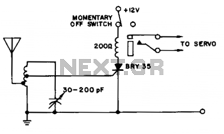
A simple and effective receiver for actuating garage doors, alarms, warning systems, etc. The SCR, which has a very low trigger current of 30 µA, requires an input power of only 30 µW to activate the relay. A high...
Low distortion bass and treble control for an amplifier. Circuit diagram. Electronics project. The low distortion bass and treble control circuit is designed to enhance the audio quality of an amplifier by allowing precise adjustments to the low and high-frequency...