
Control 32 DAC channels via a parallel port

The described circuit operates as a multi-channel digital-to-analog converter (DAC) system, leveraging the capabilities of eight DAC7615 devices to control 32 independent voltage outputs. Each DAC7615 is a 12-bit device, allowing for precise voltage control across a defined range of -2.5V to +2.5V, determined by the configured reference voltages. The architecture utilizes the parallel port of a PC, which provides both data and control signals necessary for programming the DACs.
The data transmission to the DACs is organized in a structured manner, with each DAC receiving a 16-bit word that includes address bits, dummy bits, and the actual data bits. This ensures that each DAC can be uniquely addressed and updated without affecting the output of the other DACs until all channels are programmed and updated simultaneously.
The use of OPA4277 operational amplifiers to buffer the reference voltages ensures that the reference levels remain stable and consistent across all DACs, enhancing the accuracy of the output voltages. The double-buffered input feature of the DAC7615 allows for seamless updates to the outputs, facilitating dynamic changes in the output voltages without glitches.
The software component of the system is crucial, as it prepares the data for transmission in a format compatible with the parallel port. This involves converting the data into a series of 8-bit words that can be efficiently sent to the DACs. The cyclic nature of the data transmission—where each DAC's channels are programmed in sequence—ensures that all outputs can be controlled in a synchronized manner, which is essential for applications requiring coordinated voltage outputs.
Overall, this circuit design exemplifies a robust approach to multi-channel DAC control, integrating hardware and software components to achieve high-performance voltage output management from a standard PC interface.The circuit in Figure 1 controls 32 voltage-output channels from the parallel port of a PC. The circuit comprises eight DAC7615 quad voltage-output, serial-data programmable, 12-bit DACs. The controlling PC individually programs each of the 32 DAC channels, and all DAC outputs simultaneously update. The parallel port's eight data-output lines provide serial data into each of the eight quad DAC7615s.
The remaining four control lines of the parallel port provide the serial-data clock, input-register clock, DAC-register clock, and DAC-reset functions. Each DAC7615 has a reference high and low input, which the circuit connects to external reference voltages of 2.5V and –2.5V, respectively.
Two OPA4277 quad op amps buffer the ±2.5V DAC reference voltages. Because all of the DACs use the same ±2.5V reference voltages, all DAC outputs track together as a function of these references. The resulting DAC output-voltage range for all 32 channels is –2.5V to +2.5V.
The circuit programs each of the eight DAC7615s by shifting in a serial 16-bit word comprising two address bits, two dummy bits, and the DAC 12-bit data word. The serial data for the VOUTA channel of each DAC7615 shifts in first, followed by the VOUTB , VOUTC , and VOUTD channels.
The DAC7615s have a double-buffered data input, so the circuit can load the programmed data for all DAC channels into input registers without changing the previously set DAC output voltage. After each 16-bit word shifts into the corresponding DAC7615, the DAC control line momentarily pulses low to latch the shifted data into each DAC's internal input register.
Finally, when the circuit has programmed all DAC input registers, the signal pulses low to update the internal DAC registers and change all DAC outputs. To use the parallel port for simultaneous serial data transmission to all DAC7615s, the software must first manipulate the digital output data to place it in a form that can stream out the parallel port.
The controlling software transposes a group of eight 16-bit words, representing the codes to shift into each DAC7615, into a group of 16 8-bit words (Figure 2). The resulting vector of 16 8-bit words represents the 16-bit serial data stream, which the circuit simultaneously shifts into the selected one-of-four registers of the DAC7615s.
This transposition repeats four times to program all four channels of each DAC7615.
Related Circuits

As the only electronics engineer in the family and circle of friends, it is sometimes challenging to decline requests for assistance. Recently, a friendly elderly lady in a retirement home sought help regarding her lighting situation. In her room,...
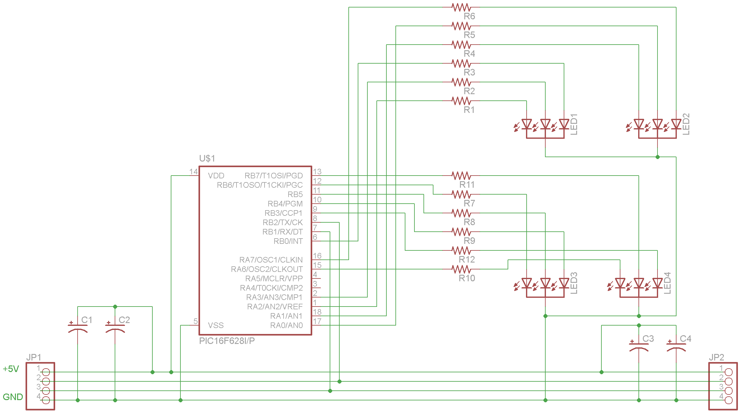
The complete schematic for the driver is provided. A PIC16F628 microcontroller has been selected due to its low cost, internal oscillator (4 MHz), and built-in USART. It is important to note that there is an error in the schematic;...
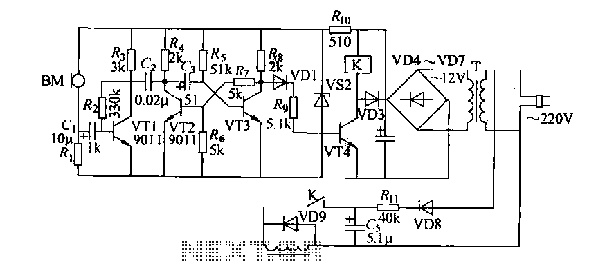
Cook in advance to open the door with a coal stove; before using the fire, it should be strong. This is an automatic door opening device that can automatically open the door before the regular homeowner, eliminating the need...
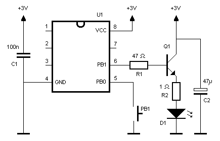
An infrared (IR) remote control designed for a Nikon DSLR camera. While not essential, it serves as an interesting project. The protocol used by the original Nikon remote controls ML-L1 and ML-L3 is straightforward, as explained by Big Mike...
This circuit is a simple manual analog light control desk that outputs standard 0-10V control signals suitable for controlling professional light dimmers and other lighting equipment. The controller's output is a steady DC voltage that varies between 0 and...

PICLink RS232 low-cost development controller with ADC. The PICLink RS232 embedded controller module provides any microcontroller with RS232 communication capabilities. The PICLink RS232 embedded controller is designed to facilitate communication between microcontrollers and RS232 devices, making it an essential component...