
Light dimmer controller desk

It is encouraged that the control signal be isolated from earth ground. The short circuit protection in this circuit is provided in case when the power supply powering this circuit has limited output current capability. The control signals are fully isolated in this design. ESTA E1. 3, Entertainment Technology - Lighting Control System - 0 to 10V Analog Control Protocol, Draft 9 June 1997 (CP/97-1003r1) describes also that controllers and output devices shall be provided with a blocking diode (or similar circuit) such that each output presents an open circuit to any source voltage of more than itself.
The blocking diodes allow multiple controllers or outputs to be paralled to control the same dimmers or receivers on a "highest takes precedence" basis. My design does not include those blocking diodes bacause I did not feel that parallelling of many controllers was necessary in the simple applications where I planned to use this controller.
If you need to parallel multiple controllers then you can add the blocking diodes, but be warned that this causes some nonlinearity to the control signal. This lighting control circuit diagram is very simple. It just consists of voltage regulator (LM317 and R1) and the potentiometers. The regulator gives out regulated +10V voltage and the potentiometers adjust the output voltages. The voltage regulator needs to be adjusted to give out exactly 10V output voltage. The output voltage is adjusted by turning trimmer R1 and checking the output voltage with a multimeter.
Adjustable outrput voltage makes it possible to adjust the board also to other control voltage standard (those are quite rate but exist in some applications). The regulator IC does not need any special heatsink this this circuit because the output current needed from it is quite slow (around 40 mA + current taken from the outputs).
Good mechanical construction is essential for reliable operation. The circuit does not need any special shielding because the DC control signals are not very sensitive to interference. A good small plastic case is ideal for this application but you can as well use a metal case. Because there is so small number of components in this circuit you don`t necessarly need to make any special circuit board for this circuit.
The wiring can be made directly from the potentiometer to potentiometer. The regulator IC can be fitted near the power input connector quite easily. The potentiometers R2. R5 should be linear type because the 0 to 10V control is intended to be linear. The best type of potentiometer to use is the potentiometers with linear slider construction because you get in this way the touch and feel of a real lighting desk. You can also use rotary dial potentiometers but the usability of the desk will suffer from that. You can use whatever output connector you want for the signl output. The connector selection depends on the equipment you want to control. Good choices for connectors are for example 9 pin and 25 pin D connector. Controllers or sending devices are recommended to use connectors with female contacts (sockets) if suitable connector is available.
I recommend you to use 🔗 External reference
Related Circuits
The shaft can be positioned at specific angular positions by sending a coded signal to the servo. As long as the coded signal is present on the input line, the servo will maintain the angular position of the shaft....
The water level controller circuit described here controls the water level inside a tank. There are two modes available with this water level controller circuit. The water level controller circuit is designed to maintain the water level within a specified...

This design utilizes standard metal gate CMOS logic rather than the typical PIC or custom chip. A 22µF capacitor charges during one half of the AC cycle and provides trigger current to the triac during both halves. The circuit employs...
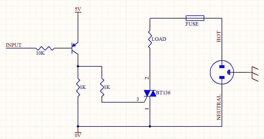
A circuit was designed to function as a light dimmer, utilizing a BT136 SCR and an MOC3022 optocoupler. However, the circuit did not operate as intended. The circuit aims to control the brightness of a light source through phase control...
As a cyclist, there is a constant search for methods to enhance visibility during nighttime rides. The concept of the `NITE-RIDER` was developed to create a distinctive and attention-grabbing rear light for bicycles. This design features nine extra-bright LEDs...
The circuit consists of two 555 timer oscillators configured in a dual timer arrangement, both set up in astable mode. Components include a 1N4148 diode and a 555 integrated circuit. The dual 555 timer circuit operates in astable mode, generating...