
remote control mains switch

To implement the solution for the elderly lady's lighting needs, a wireless power outlet can be used to control the standing lamp from a distance. The circuit design will involve a prototyping board where connections are made to the wireless remote control's push buttons. The following steps outline the process:
1. **Components Required**:
- Wireless power outlet with remote control.
- Prototyping board (suitable size to fit the remote control).
- Wires for soldering.
- Soldering iron and solder.
- Enclosure for housing the remote and prototyping board.
2. **Circuit Design**:
- Open the wireless remote control carefully to access the internal push buttons.
- Identify the connections for the "on" and "off" buttons. This may require a multimeter to trace the circuit paths.
- Solder wires to the contacts of the "on" and "off" buttons. These wires will connect to the prototyping board.
- On the prototyping board, create a simple circuit that connects the soldered wires to a pair of momentary push buttons. This setup will allow the existing wall switch and pull cord to control the standing lamp.
3. **Wiring and Assembly**:
- Ensure that the prototyping board is securely mounted within the enclosure, allowing easy access to the push buttons.
- Connect the wires from the prototyping board to the corresponding terminals of the wireless remote control.
- Test the assembly by pressing the new push buttons to ensure that they successfully operate the standing lamp.
4. **Final Considerations**:
- Ensure all connections are secure and insulated to prevent short circuits.
- Consider labeling the buttons for clarity, especially for the elderly user.
- Place the enclosure in a convenient location near the existing light switches for ease of use.
This approach not only provides a practical solution for the elderly lady's lighting needs but also enhances her independence by allowing her to control the standing lamp from her bed without the need for a traditional light fitting.As the only electronics engineer in my family and circle of friends, it is sometimes not possible to evade an appeal for help. This time the request came from a friendly elderly lady in a retirement home. In her room the light switch by the door and the pull cord above the bed operate the light fitting on the ceiling in the middle of the room.
How ever, she would prefer that her standing lamp was operated by these switches instead, since she does not actually have a light fitting mounted on the ceiling. This standing lamp has an on/off switch in the power cord and is plugged into a power point. However, it stands rather far from the bed so that she always has to find her way in the dark. A wireless operated power point is not really a consideration, because it is just a matter of time before the remote is lost.
Or maybe not Behold a feasible circuit. Buy a wireless power point and an enclosure that is big enough for the remote control and a small piece of prototyping board. On the proto-typing board build the circuit according to the accompanying schematic and (carefully) open the remote control and solder wires to the push buttons for ½on ½ and ½off ½.
🔗 External reference
Related Circuits

This Low Dropout Voltage (LDO) solar charge controller employs a differential amplifier and a series P-channel MOSFET linear regulator, which work exceptionally well together. The output voltage is adjustable and primarily designed for charging 12V lead-acid batteries. The input...
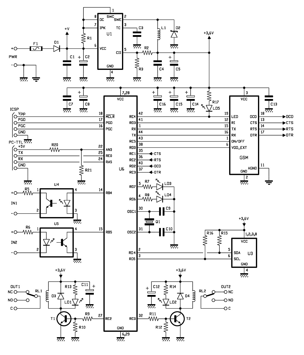
The control of the system is managed by a Microchip PIC18F46K20-I/PT microcontroller, which is programmed with firmware to oversee the activity of the GSM/GPRS module, monitor the logic conditions of two opto-isolated inputs, and send commands to two relays...
This universal triac controller circuit with optocoupler addresses the issue that triacs face when operating at low temperatures, as they require a higher gate trigger voltage. The universal triac controller circuit is designed to enhance the performance of triacs, particularly...
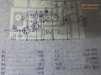
This circuit is a 220V AC lamp touch dimmer. By simply touching the dimmer, it is possible to adjust the light intensity of incandescent lamps in three stages. The touch dimmer utilizes an 8-pin CMOS IC, specifically the TT8486A...
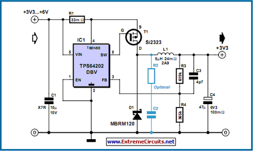
The TPS6420x controller is designed to operate from one to three series-connected cells or from a 3.3 V or 5 V supply obtained from a USB port. At its output, it can produce 3.3 V at 2 A, suitable...
The A3952S stepper motor controller, designed by Allegro MicroSystems, can be utilized to create a straightforward and effective motor driver circuit suitable for various electronic applications. This controller supports continuous output currents of up to 2 A and operates...