
Control A Relay from PIC Microcontroller

The circuit for controlling a relay with a PIC 16F628 microcontroller consists of a few essential components: the microcontroller itself, the relay, a transistor, a diode, and a power supply. The PIC 16F628 is an 8-bit microcontroller from Microchip Technology that has several input/output pins, including the RB5 pin, which is utilized to control the relay.
In this configuration, the RB5 pin is connected to the base of a transistor, which acts as a switch to control the relay. When the RB5 pin goes high, it sends a signal to the base of the transistor, allowing current to flow from the collector to the emitter. This action energizes the relay coil, causing the relay to switch its contacts and complete the desired circuit.
A diode is placed in parallel with the relay coil to protect the transistor from back EMF generated when the relay is de-energized. This back EMF can damage the transistor if not properly managed. The diode should be oriented such that it does not conduct during normal operation but will conduct when the relay is turned off, providing a path for the inductive kickback.
The power supply for the circuit must be appropriate for the relay being used, as relays typically operate at 5V, 12V, or 24V, depending on their specifications. It is crucial to ensure that the microcontroller and the relay are powered by compatible voltage levels to avoid damage to the components.
Overall, this simple circuit demonstrates the fundamental principles of using a microcontroller to control a relay, showcasing the integration of digital control with electromechanical components in various applications, such as automation and remote switching.Simply you can control a relay through Pic Microcontroller. See a simple circuit for controlling a single relay with pic 16f628. When RB5 port of pic become High the relay will operate. This Circuit works with non-latching ralays(commonly used relays are non-latching) 🔗 External reference
Related Circuits
SPICE is the most commonly used analog circuit simulator today and is enormously important for the electronics industry. SPICE is a general purpose analog simulator which contains models for most circuit elements and can handle complex nonlinear circuits. AIM-Spice...
The ELM622 by ELM Electronics is a preprogrammed PIC that converts commands from a Sony infrared remote control into a serial data stream. An IR receiver utilizing the ELM622 does not require kernel modifications. This project demonstrates how to...

This single-chip circuit adjusts its audio gain according to the ambient noise picked up by the microphone. When operating in a quiet environment, the audio output is quiet, while a noisy environment results in a louder audio output. Audio...
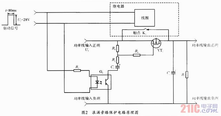
During the power-up of the apparatus, the capacitor is primarily responsible for the emergence of surge current. The schematic diagram of the principle is illustrated in Fig. 1. After K1 closes, the capacitor begins to charge, assuming that the...
The electric car remote control circuit diagram enables the model car to move forward and backward, as well as turn left and right. It is simple and easy to operate. The radio remote control receiver demodulation circuit utilizes TWH9238...
A step-down circuit is utilized to approximately halve the RMS voltage between the line input and the inductive load (L1), as illustrated in the circuit diagram below. A turn-on delay of about 7 ms is achieved through the combination...