
control circuit for nokia tv tuner 5827

The described tuner system utilizes the I²C-Bus for communication, allowing for efficient programming and control. The FBAS (Full Bandwidth Amplitude Signal) output provides a composite video signal suitable for various display applications. The integration of an AT89C2051 microcontroller enables the implementation of a robust control circuit, capable of managing the tuner’s functionality and user interface.
The user interface consists of three keys: the C/P key, which toggles between displaying the program number and the channel number, and the + and - keys, which facilitate navigation through the available channels or programs. This design emphasizes user-friendliness, allowing for intuitive operation.
Channel settings are preserved in an EEPROM (Electrically Erasable Programmable Read-Only Memory), ensuring that user preferences are retained even when the device is powered off. The use of EEPROM is advantageous for applications where channel configurations need to be saved and restored reliably.
The display is implemented using either a four-digit LC (Liquid Crystal) or LED (Light Emitting Diode) display, providing clear visual feedback to the user. The choice between LC and LED displays can be dictated by factors such as power consumption, visibility in various lighting conditions, and design preferences. The display is also controlled via the I²C-Bus, allowing for seamless integration with the microcontroller and simplifying the overall circuit design.
In summary, this tuner circuit design demonstrates a sophisticated approach to programmable tuning, combining modern microcontroller technology with user-friendly interface elements and reliable data storage solutions. The use of I²C-Bus for both control and display management highlights the efficiency and versatility of this electronic system.The tuner is programmable via I ²C-Bus and provides a FBAS signal at its output. There is also the homepage of Georg Acher containing information about this tuner. I have developed a control circuit for this tuner which uses the AT89C2051 from Atmel. Operating is done via three keys: key C/P switches between the program number and the channel number, with keys + and - you can switch up or down. The adjusted channels are stored in an EEPROM. The program or channel number is displayed on a four digit LC- or LED-Display which is controlled via I ²C-Bus. 🔗 External reference
Related Circuits
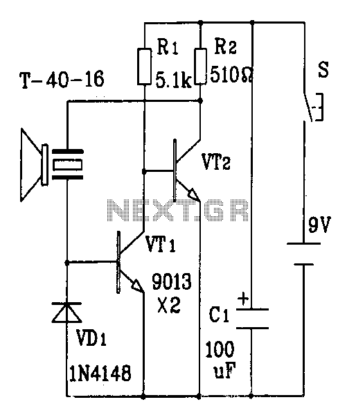
The discrete components ultrasonic transmitter circuit T/R-40-16 can emit a series of ultrasonic signals at a frequency of 40 kHz. This circuit operates at a voltage of 9V and has a current consumption of 25mA, with a control distance...
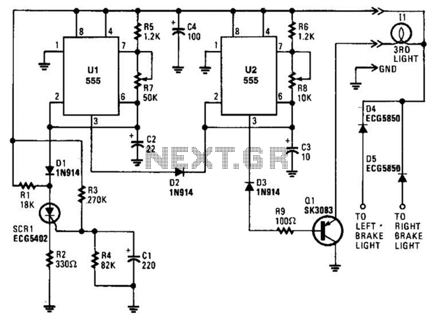
When power is first applied, three events occur: the light-driving transistor (Q1) is activated due to a low output from U2 at pin 3; timer U1 begins its timing cycle, with the output at pin 3 going high, which...
A ringer interface circuit is designed to buffer the output of a central telephone system, which connects to multiple ringers distributed throughout a building. This circuit addresses an issue where the line overloads when ringing, requiring a reset. The...
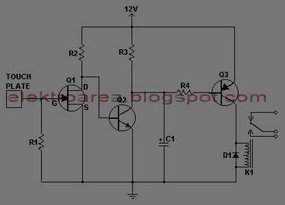
This document describes a series of touch switches that utilize only three transistors. These touch-based transistor switches can activate a load simply by the user touching a metal plate. They are designed to directly switch a relay, enabling operation...
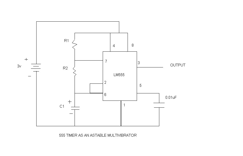
An astable multivibrator, commonly referred to as a free-running multivibrator, is a circuit that generates rectangular waves without the need for external triggering. The timing characteristics of this circuit are determined by the values of the resistors and capacitors...
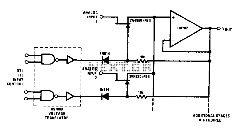
This analog switch utilizes the 2N4860 JFET, which features a low on-resistance of 25 ohms and minimal leakage current. The LM102 is employed as a voltage buffer in the circuit. Additionally, this configuration can be modified for use in...