
Control Electrical Appliances Using PC Circuit

The described circuit utilizes the parallel port of a PC, specifically leveraging the data lines D0 to D7 for control applications. The primary function of this setup is to allow a PC to control multiple devices (up to eight) through the use of software that interfaces with the printer port. Each of the data bits corresponds to a specific control line for the connected devices, enabling straightforward binary control.
In the schematic, the circuit is designed around a single device controlled by the D0 data line, which is connected to pin 2 of the 25-pin parallel port. To extend control to additional devices, similar circuits must be constructed for each of the remaining data lines (D1 to D7), which correspond to pins 3 through 9 of the parallel port.
The inclusion of an opto-coupler in the design is a critical aspect, as it provides electrical isolation between the PC and the relay driver circuitry. This isolation is important for protecting the PC from potential voltage spikes or noise generated by the connected devices. The opto-coupler allows the control signal from the parallel port to safely trigger the relay, which can then switch higher power loads without risking damage to the PC.
In practical applications, each relay can be configured to control various equipment such as lights, motors, or other electronic devices. The software running on the PC can send signals to the parallel port, which are interpreted by the interface circuit to activate or deactivate the relays as required. This setup is beneficial for automation tasks, remote control applications, or any scenario where multiple devices need to be managed from a central PC system.
Overall, this circuit provides a versatile and effective means of controlling external devices using a standard PC printer port, with the added safety of isolation through the opto-coupler.Here is a circuit for using the printer port of a PC, for control application using software and some interface hardware. The interface circuit along with the given software can be used with the printer port of any PC for controlling up to eight equipment .
The interface circuit shown in the figure is drawn for only one device, being controlled by D0 bit at pin 2 of the 25-pin parallel port. Identical circuits for the remaining data bits D1 through D7 (available at pins 3 through 9) have to be similarly wired.
The use of opto-coupler ensures complete isolation of the PC from the relay driver circuitry. 🔗 External reference
Related Circuits
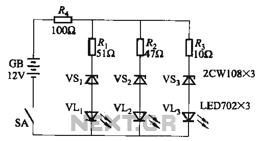
When the supply voltage falls below 10.2V, the yellow light-emitting diode (LED) VLi illuminates, indicating that the storage pool can no longer continue to discharge. Additionally, when the voltage exceeds 16.2V, the yellow, green, and red light-emitting diodes (LEDs)...

Automatic electronic refrigerator deodorant sterilization circuit The automatic electronic refrigerator deodorant sterilization circuit is designed to eliminate odors and sterilize the interior of a refrigerator. This circuit typically employs a combination of sensors, microcontrollers, and sterilization techniques to achieve effective...
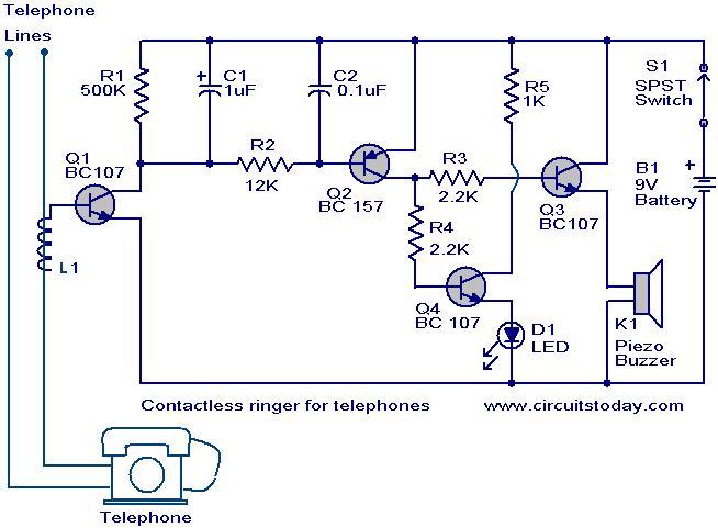
The contactless telephone ringer circuit is designed to produce an audible ring and a visual indication when a call is received. Its primary advantage lies in the absence of direct contact between the telephone line and the circuit, which...
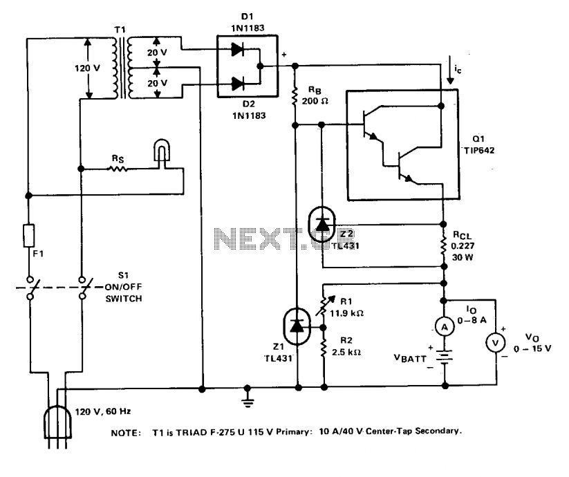
The charger operates with a charging voltage of 2.4 V per cell, aligning with the recommendations of most manufacturers. The circuit delivers a charging voltage of 14.4 V (6 cells at 2.4 V per cell) in a pulsed manner...
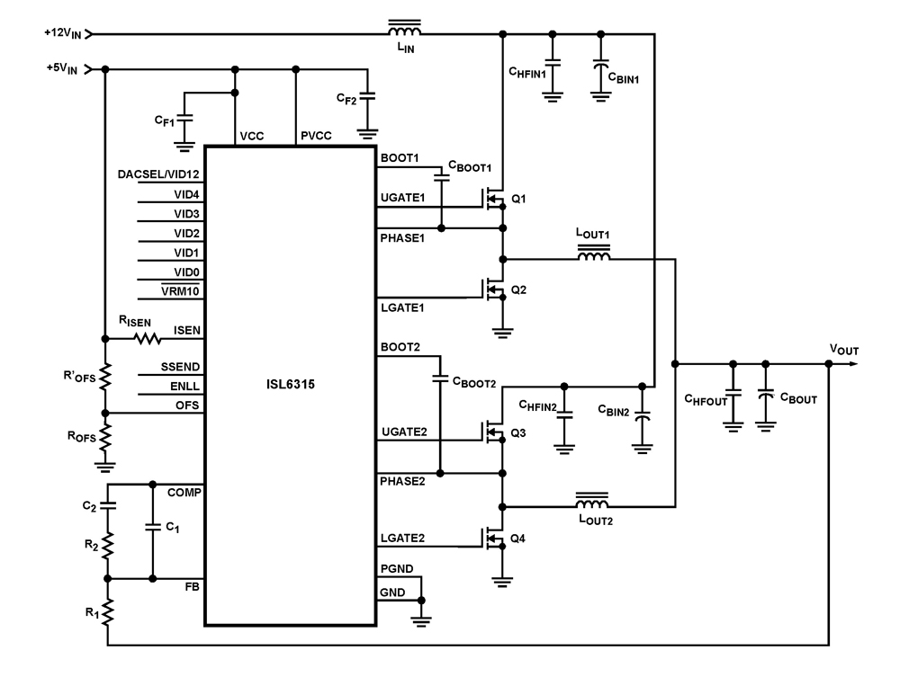
The ISL6315 two-phase PWM control integrated circuit (IC) offers a precise voltage regulation system capable of handling advanced loads ranging from 60A to 80A. Multiphase power conversion represents a significant shift from traditional single-phase converter configurations, which are increasingly...
The gate-source voltage required to bias the transistor into the linear region can range from 0.25V to 8V, resulting in a potential variation of 7.75V down to a minimal 0.4V for the transistor and load when used with a...