
Control the speed of a DC motor with a potentiometer with an Arduino board

This circuit utilizes an Arduino microcontroller to adjust the speed of a DC motor through a potentiometer. The potentiometer acts as a variable resistor, allowing the user to change the voltage signal sent to the Arduino. The Arduino processes this input and adjusts the output signal accordingly.
The TIP120 transistor is employed as a switch to control the larger power supply required by the DC motor. When the Arduino sends a PWM (Pulse Width Modulation) signal to the base of the TIP120, it allows current to flow from the collector to the emitter, powering the motor. The TIP120 can handle higher currents, making it suitable for driving motors that require more power than the Arduino can supply directly.
The circuit typically includes the following components:
1. Arduino Board: The microcontroller that processes input from the potentiometer and controls the TIP120.
2. Potentiometer: A variable resistor that allows the user to set the desired motor speed.
3. TIP120 Transistor: A Darlington pair transistor used to switch the motor on and off and control its speed.
4. DC Motor: The load that is being controlled, which varies its speed based on the potentiometer setting.
5. Diode: A flyback diode is often included across the motor terminals to protect the circuit from voltage spikes generated when the motor is turned off.
6. Power Supply: A separate power source that provides the necessary voltage and current to drive the motor.
The connections are made as follows:
- The potentiometer is connected to one of the analog input pins on the Arduino, with its other terminals connected to ground and the 5V supply.
- The base of the TIP120 is connected to a PWM-capable digital output pin on the Arduino through a current-limiting resistor.
- The collector of the TIP120 is connected to one terminal of the DC motor, while the other terminal is connected to the positive side of the external power supply.
- The emitter of the TIP120 is connected to ground.
- The flyback diode is placed in parallel with the motor terminals, oriented to allow current to flow back to the power supply when the motor is turned off.
This setup allows for smooth control of the motor speed, providing an effective solution for various applications requiring variable speed control.A quick circuit showing how to control the speed of a DC motor with a potentiometer with your Arduino board. Also shows how to use a TIP120 transistor to allow the Arduino control a larger power supply. 🔗 External reference
Related Circuits
The performance indices of the telecontrol receiving decoding circuit are as follows: radio frequency (f) = 27 MHz, audio frequency (f) = 5.5 kHz, 100% modulation in square-wave form; radio frequency deviation is ±600 Hz, and the frequency shift...
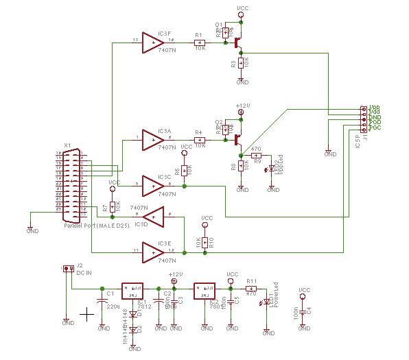
Schaer is a generic programmer circuit capable of uploading and downloading firmware to and from several electronic devices, such as microcontrollers. The Schaer programmer circuit is designed to facilitate the transfer of firmware between a host computer and various electronic...
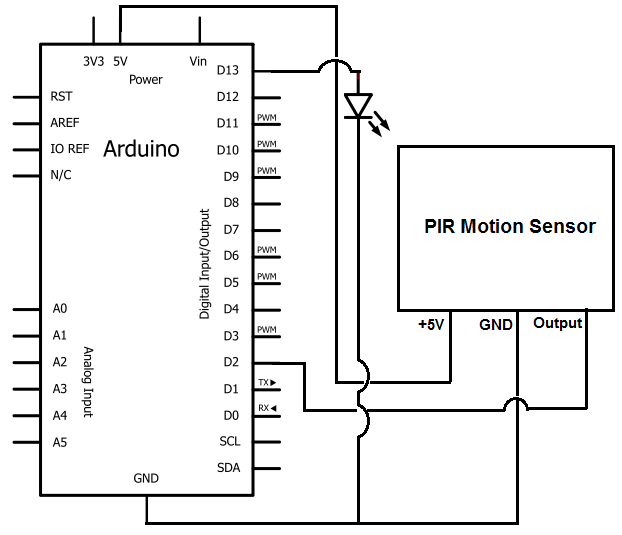
Once the motion sensor detects motion, the Arduino can be programmed to activate an LED, turn on a motor, sound a buzzer, etc. In this circuit, for simplicity, an LED will be turned on when the motion sensor detects...
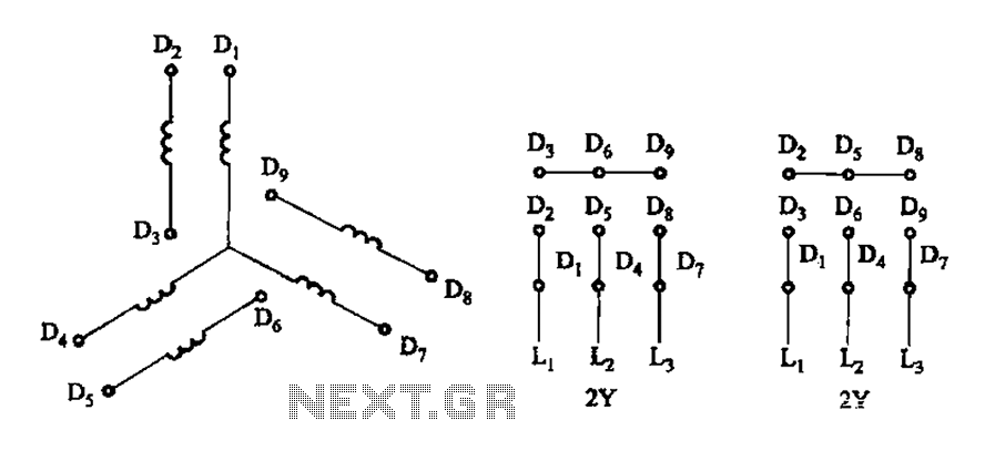
As illustrated in Figure 3-105, this diagram depicts the lead wiring configuration for a two-speed motor stator with a 2Y/2Y connection. The two-speed motor stator wiring diagram is essential for understanding the configuration and operation of the motor. In this...
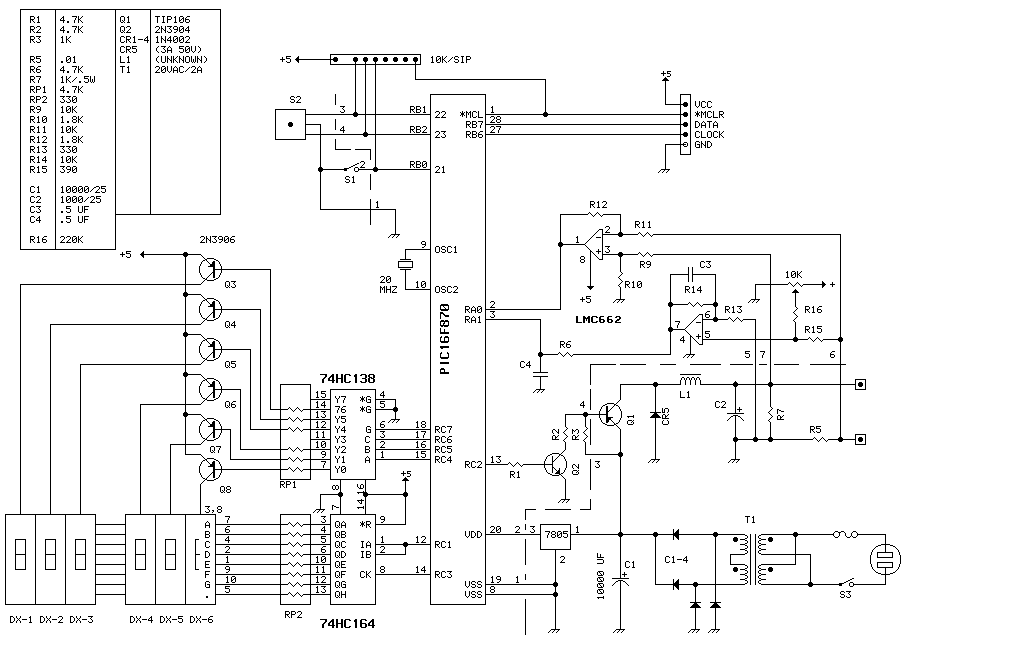
This unit delivers 0 to 20 volts at up to 4 amps in 0.1 volt increments. The entire device runs on a PIC16F870 (about $3 in small quantities). This is basically a switching power supply with the voltage regulation...

The Project Long Range Remote Control can be used to remotely control a number of Electrical or Electronic Gadgets connected to it. Unlike Infra Red remote control, this Project employs FM transmission and Reception, and hence it can be...