
LM909 radio telecontrol receiving decoding circuit diagram

The telecontrol receiving decoding circuit is designed to operate at a radio frequency of 27 MHz, which is a common frequency for remote control applications. The audio frequency of 5.5 kHz indicates the frequency at which the audio signal is processed, allowing for effective communication between the transmitter and receiver. The circuit utilizes a square-wave modulation technique, achieving 100% modulation depth, which ensures that the transmitted signal maintains its integrity and is easily distinguishable from noise.
The circuit's frequency deviation of ±600 Hz indicates the range within which the carrier frequency can shift during operation, allowing for reliable signal detection. The use of frequency shift keying (FSK) at 160 Hz enables the transmission of binary data by shifting between two frequencies, which is essential for digital communication in telecontrol systems.
The duty factor, adjustable to 100%, 60%, or 30%, allows for variations in the on/off time of the transmitted signal, impacting the power consumption and responsiveness of the circuit. This flexibility is crucial for optimizing performance based on specific application requirements.
Transformers T1 and T2 play a vital role in the circuit's operation. T1, with a primary winding of 10 turns and a secondary winding of 4 turns, is likely used for impedance matching and signal coupling. The turns ratio of 2.5:1 suggests that the transformer steps down the voltage from the primary to the secondary side, which can be advantageous for interfacing with low-voltage circuits. T2, with a primary winding of 12 turns, serves a similar function, potentially providing additional signal conditioning or isolation.
Overall, the telecontrol receiving decoding circuit is engineered to ensure reliable communication and efficient signal processing, making it suitable for applications in remote control systems, wireless data transmission, and other related fields.The telecontrol receiving decoding circuit`s performance index shown as the chart are as follow: f radio frequency =27MHz, f audio frequency =5.5KHz, 100% modulation - square-wave; f radio frequency=±600Hz, and the frequency shift keying (FSK) is 160Hz, and the dutyfactor is 100%, 60% or 30%, T1`s primary is 10T, secondary is 4T; T2`s primary is 12T, second.. 🔗 External reference
Related Circuits
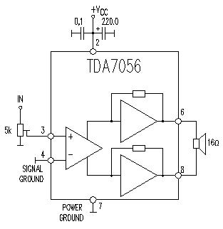
This TDA7056 power audio amplifier circuit diagram project is designed to deliver a maximum output power of 1 watt into an 8-ohm load when powered by a 6-volt supply, or a maximum output power of 3 watts into a...
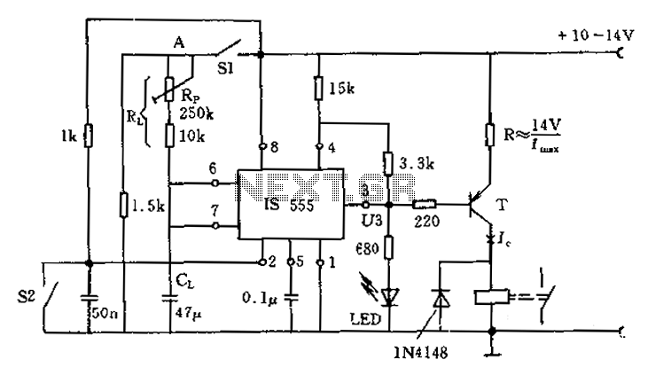
The circuit for the photoelectric switch S1 functions as a control switch for the luggage room light. In its closed operating state, the voltage is positive. If S2 is closed, irrespective of the state of S1, the output terminal...
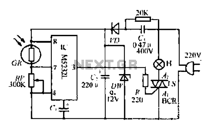
The DW L11 capacitor steps down voltage into the Jenru half crossing according to Yin electrical specifications. After receiving power at the bin CI SH output terminal, it regulates the voltage to liVI/r j, ensuring a right cut in...
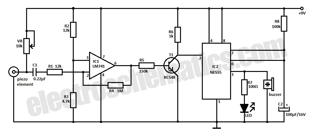
This is an ultra-sensitive earthquake detector circuit capable of sensing seismic vibrations. It can be utilized to detect vibrations in the Earth. The ultra-sensitive earthquake detector circuit is designed to respond to minute seismic vibrations, making it an essential tool...
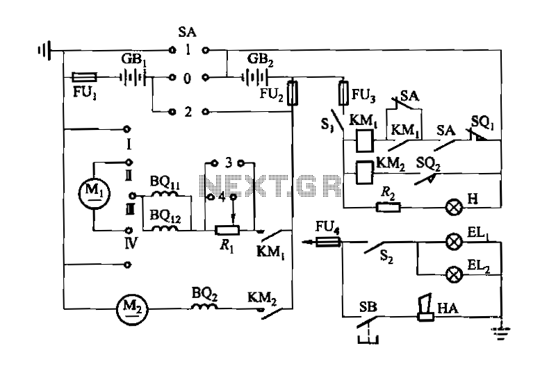
Denote cam controller SA 1 contact closure case. M1 is 1.35 kW driving motor, M2 is a 4 kW pump motor. The circuit involves a cam controller designated as SA 1, which is responsible for managing the operation of...
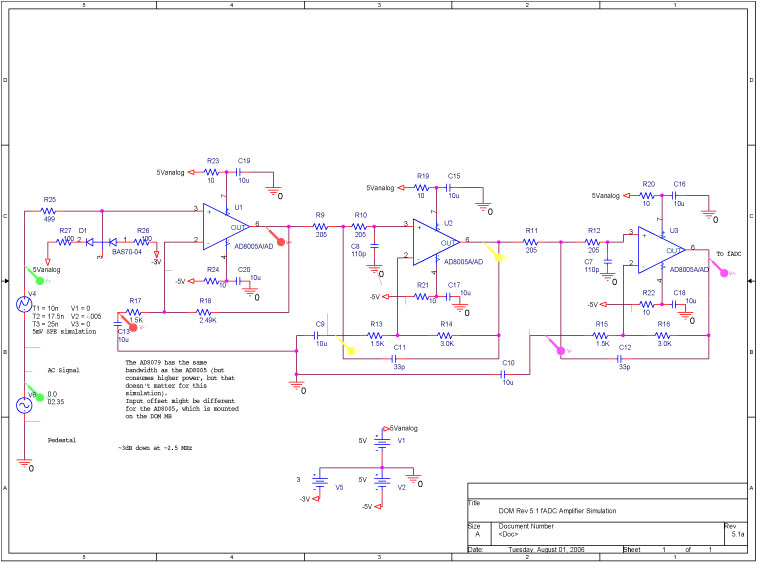
A bandwidth-limited amplifier shapes the waveform sampled by the 40 MHz high-speed pipeline Analog to Digital Converter (fast ADC, or fADC). It is well known that the shaping time is twice the time constant (peaking time) for each pole...