
Two-speed motor stator winding 2Y-2Y connection

The two-speed motor stator wiring diagram is essential for understanding the configuration and operation of the motor. In this setup, the stator windings are connected in a 2Y (two-phase star) arrangement, which allows for the motor to operate at two different speeds. The diagram typically indicates the various terminals of the stator windings, showing how they connect to the power supply and the control circuitry.
In a 2Y connection, each phase of the motor is connected to a common neutral point, which reduces the voltage across each winding, thus allowing for a more efficient operation at lower speeds. The two-speed capability is often achieved by connecting different sets of windings to the power source, enabling the motor to switch between high and low speed based on the control signals received.
The diagram must clearly label the terminals, including the start and end points of each winding, as well as any additional components such as capacitors or relays that may be involved in the switching mechanism. It is crucial to ensure that the connections are made correctly to prevent any electrical faults or inefficiencies in the motor's operation. Proper understanding of this wiring diagram is vital for technicians and engineers engaged in the maintenance and troubleshooting of two-speed motors. As shown in Figure 3-105 2Y/2Y-connected two-speed motor stator windings lead wiring diagram.
Related Circuits
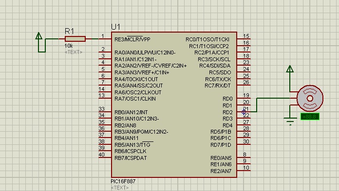
The shaft can be positioned at specific angular positions by sending a coded signal to the servo. As long as the coded signal is present on the input line, the servo will maintain the angular position of the shaft....
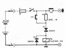
Safety polarity connection circuit design using common electronic components The safety polarity connection circuit is designed to ensure that electronic devices are connected with the correct polarity, preventing damage from reversed connections. This circuit typically employs common electronic components such...
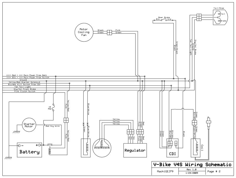
A 2005 Wildfire 250 QAC ATV is experiencing starting issues. When attempting to start, it sounds as though the starter gears are spinning without engaging. After flipping the ATV, the problem has persisted. There is a one-way clutch between...
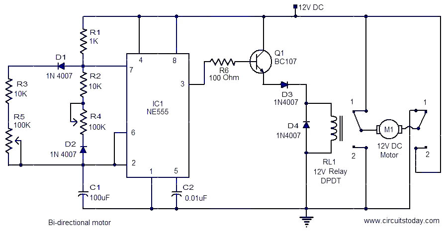
This is a simple and easy-to-construct circuit designed to provide a bidirectional drive for a DC motor. The circuit operates straightforwardly. The output of an astable multivibrator based on IC1 (NE555) is utilized to control the relay RL1 that...
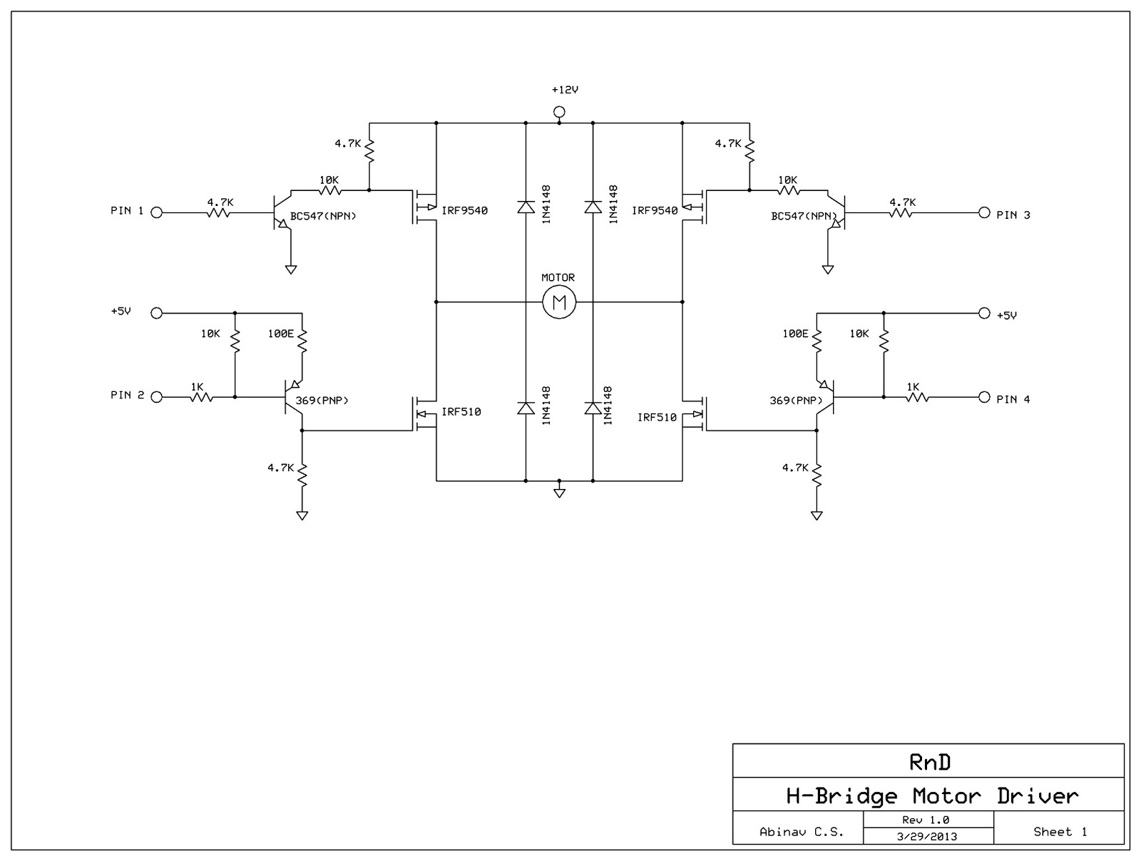
This post discusses the construction of an H-Bridge Motor Driver circuit using simple MOSFETs and transistors. The primary feature of this H-Bridge is its ability to drive a motor in both directions. An H-Bridge is a circuit that allows...
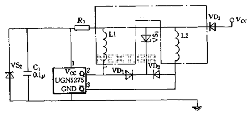
The circuit features almost open collector outputs with a withstand voltage of 60V and a continuous conduction current of 0.3A. The typical voltage drop is 0.4V, with a peak current capability of 9A. It can directly drive two windings...