
controller

The circuit described utilizes a 741 operational amplifier as the heart of the thermal control system. The thermistor, a temperature-sensitive resistor, plays a crucial role in detecting temperature changes. As the ambient temperature increases, the thermistor's resistance decreases, affecting the voltage at the op-amp's input. The op-amp is configured in a comparator mode, where it compares the voltage from the thermistor with a reference voltage set by resistor R4. When the temperature surpasses the predetermined threshold, the output of the op-amp transitions, switching the state of transistor Q1.
Transistor Q1 acts as a switch for the cooling fan. When activated, it allows current to flow from the power supply through the fan, thus cooling the radio equipment. The design should ensure that the fan is adequately rated for 12 volts and capable of drawing up to 200 mA. The placement of the thermistor is critical; it should be securely mounted to the heat sink to accurately measure the temperature without being influenced by the airflow from the fan.
Capacitor C1's role in the circuit is twofold: it filters any electrical noise generated by the fan, which could interfere with radio operations, and it provides a soft start for the fan motor, reducing the inrush current when the fan is activated. The appropriate value for C1 can be determined based on the specific fan used and the noise characteristics of the overall system.
In conclusion, this thermal cooling fan controller circuit provides an effective solution for managing heat in older radio equipment, ensuring reliable operation during extended use in high-temperature environments. The design emphasizes the importance of component placement and connection methods to maintain the integrity of the thermistor and overall circuit functionality.As we activate to adore those apathetic bleared canicule of summer, the best important affair on best of our minds is how to accumulate air-conditioned during those hot days. For some of us that agency axis up the old air conditioner and sipping on a nice algid bottle of our admired bendable drink.
However, we generally balloon about an appropriat ely important account and that is how to accumulate our rigs air-conditioned during those continued asthmatic summertime QSO`s. Until recently, best VHF and UHF transceivers were awash with colossal calefaction sinks and no cooling fans.
Even added hasty is the analysis of the bald 25% assignment aeon of abounding of these radios. Is it any admiration that those RF ability amplifier modules accept such a aerial abortion rate If you own one of those earlier radios advised afore manufacturers assuredly accomplished that cooling admirers were absolutely needed, advice is at hand. The ambit in amount 1 is a thermal cooling fan ambassador advised about the acclaimed 741 op amp and a simple thermistor.
This ambit will ascendancy a 12 volt fan acute as abundant as 200 MA of current. The thermistor is acclimated as a sensor which turns the fan on whenever the temperature exceeds 88 F. Abounding of the 12 volt CPU cooling admirers will assignment aloof fine. Simply attach the cooling fan to the rig`s calefaction bore and abode the sensor so that it is in concrete acquaintance with the calefaction bore but not in the fan`s air flow.
Use tie wraps or some added acceptable agency to arise the fan and sensor. Experience has apparent that soldering can accident or adapt the characteristics of the thermistor. Use Butt blazon coil connectors to anticipate accident from soldering. The thermistor, R1, is absolutely the affection of this circuit. At 70 F, the thermistor has a attrition of about 10, 000 ohms. As the thermistor heats up, it`s attrition decreases until the voltage beginning bent by R4 is reached. At this time the achievement of the op amp goes from aerial to low causing transistor Q1 to be saturated and acceptance accepted to breeze through the emitter to the collector.
Capacitor C1 acts as a clarify capacitor abbreviation fan babble as able-bodied as accouterment a capacitive alpha for the motor. Do not omit C1 in this circuit. The amount of C1 may charge to be added if fan babble becomes aural in your rig`s receiver. If you would like the fan to about-face on at a altered temperature or can`t acquisition an 8. 2K resistor in your clutter box again alter R4 with a 10K trimmer pot. 🔗 External reference
Related Circuits
The AquaCont is an electronic system which permits to manage and to monitor most of the parameters of all the electric devices that can be found in an aquarium. The PIC18F4520 used to realize it combines a real-time clock...
The objective of this project is to create a controller-based model that counts the number of individuals entering a specific room and activates the lighting accordingly. A sensor will be utilized to determine the current number of persons present....
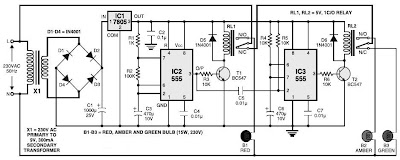
This is a simple traffic light controller that can be used to teach children the basics of traffic light rules. The circuit employs commonly available electronic components and consists of rectifier diodes (1N4001), a 5V regulator (7805), two timer...
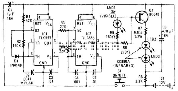
The transmitter is constructed using two CMOS 555 timer ICs (TLC 555s). It generates a modulated 35-kHz infrared signal. The carrier frequency of 35 kHz is produced by IC2, while IC1 generates a 1,500-Hz modulating signal. The output from...
Voltage regulator ICs from the 78xx series deliver a stable output voltage in contrast to a highly variable input supply, provided that the common terminal is grounded. Any voltage applied above zero volts (ground) to the common terminal is...
When the power is connected to the circuit by turning on SW2, RELAY1 gets energized for the time it takes to load C3 through R1 and R3. After that, the relay gets de-energized, and C3 gets discharged through R2...