
Infrared Remote Controller

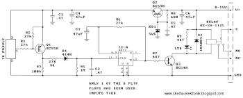
The transmitter circuit utilizes two 555 timer ICs configured in astable and monostable modes to generate the required modulated infrared signal. The first timer, IC1, operates in monostable mode to create a 1,500-Hz signal, which serves as the modulation frequency. This signal is fed into the second timer, IC2, which is set up in astable mode to produce a continuous 35-kHz carrier wave. The output of IC2 is connected to a visual indicator, LED1, through a current-limiting resistor (R5), allowing users to confirm that the transmitter is functioning correctly.
Transistor Q1 acts as a switch that controls the power to the two infrared LEDs (LED2 and LED3). When the circuit is powered, the precharged capacitor C6 provides the necessary current to drive the LEDs, ensuring they emit infrared light effectively. The precharging of C6 is accomplished while the circuit is in a standby mode, with R8 maintaining the charge when switch S1 is not pressed. Upon pressing S1, the stored energy in C6 is released, powering the infrared LEDs for a short duration (up to 0.2 seconds). This duration is designed to ensure that the receiver can pick up the transmitted signal without requiring continuous power.
The circuit design emphasizes efficiency and simplicity, making it suitable for applications where a brief burst of infrared transmission is needed. The use of CMOS technology ensures low power consumption, making it ideal for battery-operated devices. The combination of the 555 timers, the transistor switch, and the precharging capacitor creates a reliable and effective transmitter circuit for infrared communication. The transmitter is built around two CMOS 555 timer ICs (TLC 555s). The transmitter generates a modulated 35-kHz IR signal. The 35-kHz carrier frequency is generated by IC2, and the 1 500-Hz modulating signal is generated by IC1. The output of IC2 drives LED1 through resistor R5; that LED provides visual indication that the transmitter is working.
In addition, IC2 drives transistor Ql, which drives the two infrared LEDs (LED 2 and LED 3). To provide the high current needed to drive the two IR LEDs, capacitor C6 is precharged, the charge it contains is dumped when SI is pressed. When SI is not pressed, the power to the ICs is cut off. However, C6 is kept charged via R8. Then, when SI is pressed, the current stored in C6 can be used to drive the LEDs for as much as V2 second.
That"s plenty of time for the receiver to pick up a signal.
Related Circuits
All modern infrared (IR) remote control devices generate a continuous coded stream of pulses at 37.9 kHz when any button on the device is pressed. These IR pulses are received and decoded by a compatible device, such as a...
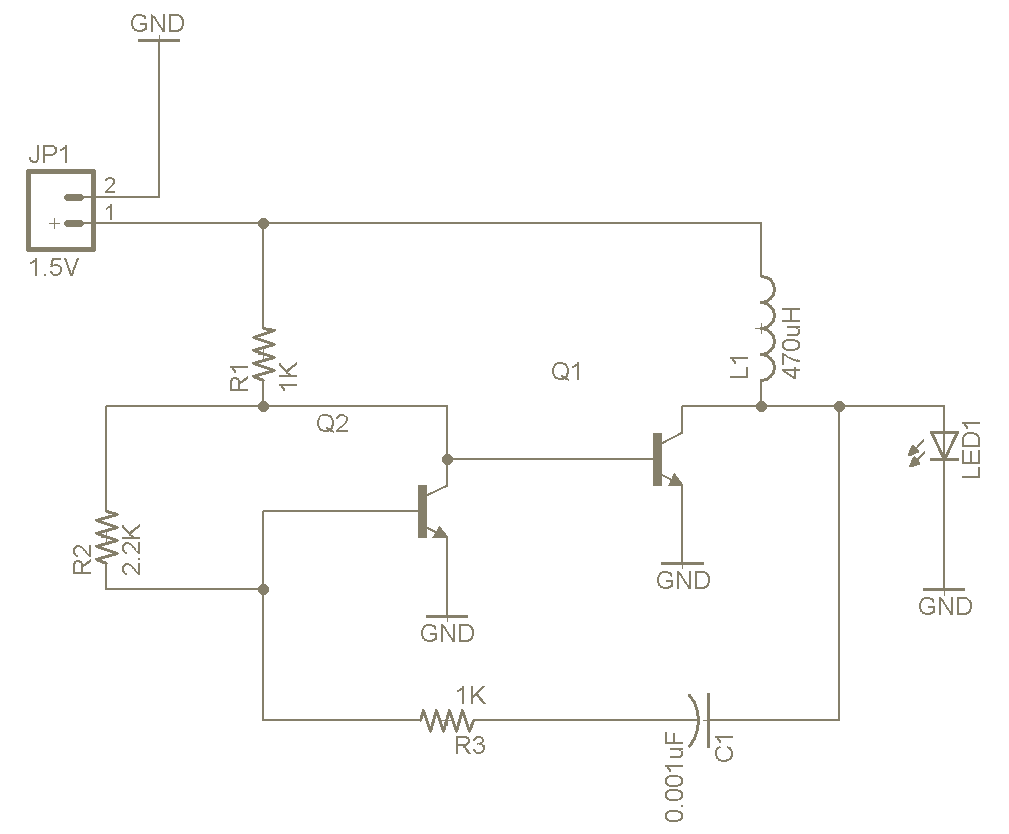
The Joule Thief is a straightforward and uncomplicated device, yet its functionality is remarkable. It can utilize a battery that is otherwise deemed unusable in any other electronic device, and it is very easy to construct on a breadboard...
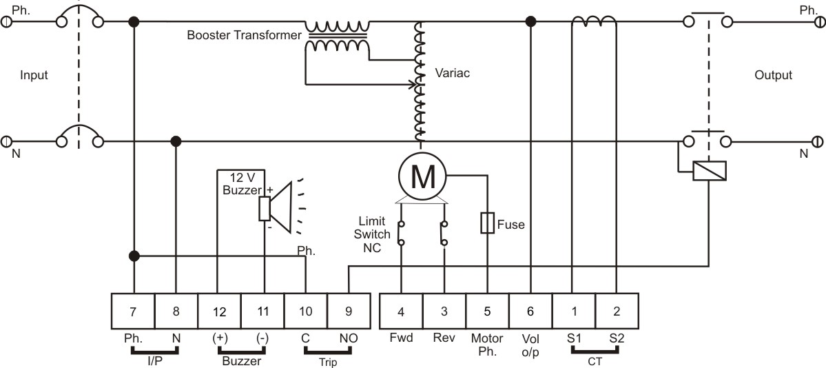
The BPS Servo Controller - Digital is a comprehensive metering and control solution designed for servo stabilizers, accommodating a wide range of input voltages and load requirements. This system minimizes production overheads such as wiring and testing, thereby enhancing...
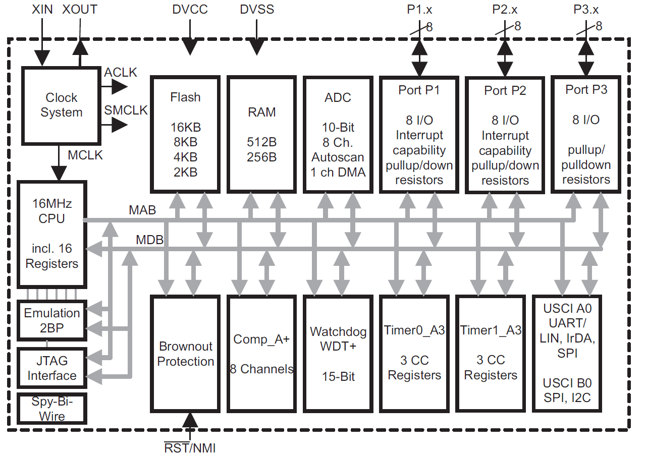
This module provides an overview of the MSP430 microcontroller, instructions on how to read its data sheet, and guidance on selecting the appropriate model for various applications. It is part of a textbook aimed at helping seniors choose Texas...
The TVT-MOBI-2 will initially display a static image and will not respond to data from its serial interface, except for one function. The internal clock can be set by providing a date and time value, allowing it to calculate...
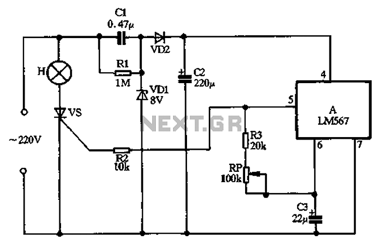
Cl, VDI, VD2, C2 form a simple capacitive step-down voltage regulator circuit with a rectifier output providing approximately 8V DC voltage for the LM567. A 5.6-foot manifold is connected. Resistors R3, RP, and capacitor C3 create an ultra-low frequency...