
Controlling stepper motors

- Absolute move: M <n> - Go to <n> location, possible values are 0 to 32767.
- Relative movement: + <n>, - <n> - From the current position +/- <n> step moves, possible values are 0 to 65536.
- Homing: R <n> - Set the location counter value to return to the origin at a constant rate of 200pps, reverse feed input until detection, then finish until the origin input. Usually, omit the (0).
- Set location counter: P <n> - Set the location counter value, 0 is equivalent to setting the value omitted.
- Set velocity: V <n> - Set the moving speed, range from 0 to 31, corresponding to 166pps ~ 1266pps unit at 33pps.
- Acceleration setting: A <n> - Set acceleration at starting and stopping, range from 0 to 15, higher values indicate gradual acceleration and deceleration.
- Excitation system settings: M <n> - Set the mode of excitation pulse motor, value between 0 and 3.
- Excitation ON/OFF: D <n> - Excitation of the motor output ON/OFF, 0 OFF (default), 1 ON. The OFF command disables pulse excitation mode.
- Step movement: "<", ">" - Run command immediately upon receiving the letter, "<" for step backward, ">" for advance in 1 step.
- Parameters read: "?" - Read P-value, V value, A value, M value.
- Store operating parameters: "_" - Store values V, A, M in EEPROM for next startup.
- Sudden stop - Break during move command signal transfer (20ms or more) for immediate stop.
- Return value - After the process, returns the result code for each command.
The pulse motor system described relies on precise control mechanisms to ensure accurate positioning and movement. The motor operates under a set of commands that dictate its behavior, allowing for both absolute and relative movements. The absolute move command (M <n>) directs the motor to a specific position within a defined range, while relative movements (+ <n> or - <n>) adjust the motor's current position incrementally.
The homing command (R <n>) is crucial for establishing a reference point for the motor's movements, ensuring that the system can return to a known state. The speed of the motor can be adjusted through the velocity command (V <n>), which allows for fine-tuning of performance based on application requirements. This is complemented by the acceleration setting (A <n>), which controls how quickly the motor can start and stop, thus enhancing operational efficiency.
The excitation system settings (M <n>) and excitation ON/OFF commands (D <n>) provide flexibility in how the motor is powered, allowing for different operational modes depending on the task at hand. Step movement commands ("<" and ">") enable immediate response to control inputs, providing real-time adjustments to the motor's position.
The ability to read parameters with the "?" command and store operating parameters in EEPROM ensures that the system retains its settings across power cycles, enhancing reliability and ease of use. The sudden stop feature allows for immediate cessation of motor activity, which is critical for safety in dynamic environments.
Overall, this pulse motor system is designed for precision control in various applications, leveraging a robust command set to enable flexible operation and efficient performance.The first pulse motor that is used to diss it because it is the positioning control things, we decided to incorporate features that may be needed for positioning control. This does not mean that intelligent, and autonomous driving the motor in response to movement commands from the host.
The key to controlling the pulse motor, the stall is to prevent slowly varying speed during starting and stopping, and of course also be applied to control and became a highlight of this feature. The parameters required for control (such as maximum speed, acceleration, excitation system) to be able to change the command.
And the host controller sends commands to the RS232C connection. And with no protocol to control communication software easily. The following gives details of each command. Absolute move: M
Parameters read: "?" P-value, V value, A value, M value is read. Store operating parameters: "_" Value V, A value, M value stored in the EEPROM. This defaults to the next startup. Sudden stop Break during the move command signal transfer system (20ms or more) to send immediate stop. Return value After the process returns the result code for each command. Support the values ??and meanings are as follows. 🔗 External reference
Related Circuits
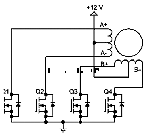
A bipolar stepper motor drive circuit is presented, utilizing eight transistors to operate two phases. This bipolar drive circuit can accommodate both four-wire and six-wire stepper motors; however, it is primarily designed for four-wire bipolar configurations, which can significantly...
A circuit that will find enough applications. Basically, the designing became in order to exist delay in quench one or more lamps in a stairwell or in any other space exists this need. It can become use for the...
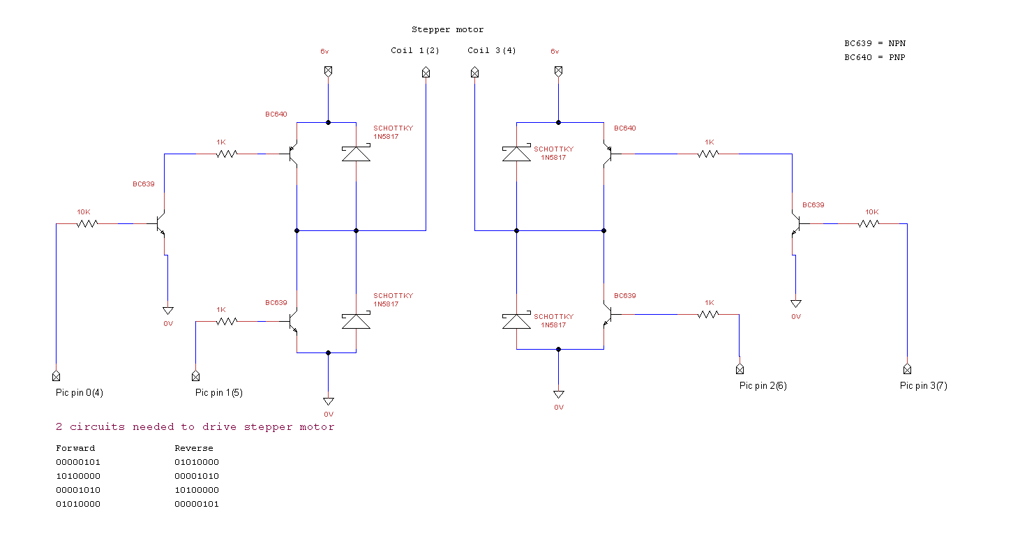
miRover. This page details how to use a PIC microcontroller and an H-bridge or an L298 to drive a bipolar stepper motor. The project involves utilizing a PIC microcontroller to control a bipolar stepper motor, which is commonly used in...
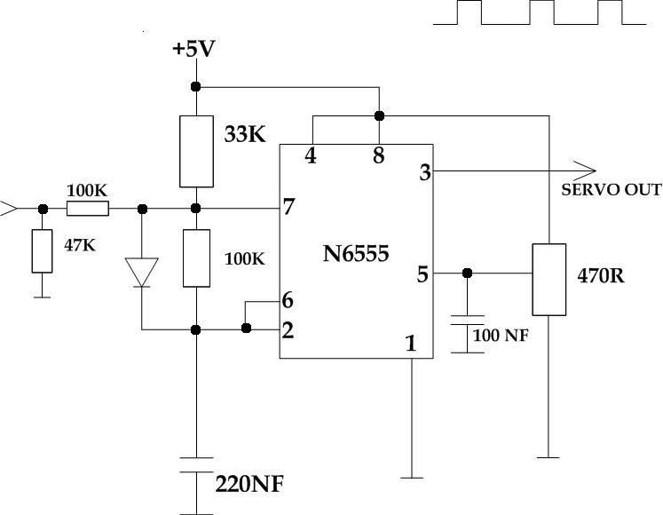
This circuit takes a standard 0-10V control voltage (for example, from an analog light control desk) and outputs a standard 1-2 ms control pulse for RC servo motors. The components used in this circuit include: - 2 x 100...
In a traditional microstepping motor controller, multiple parallel outputs from a microcontroller are utilized, which are then converted to analog signals using a Digital-to-Analog Converter (DAC) and sent through a power amplifier to drive the motor coils. This method...
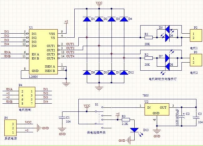
1. Driver: L298N Dual H Bridge DC Motor Driver IC 2. Supply voltage for the driven part (Vs): +5 V to +35 V; for internal board power supply, Vs: +7 V to +35 V 3. Peak current for the...