
micro stepper

The microstepping motor controller operates by utilizing a unique algorithm that allows for precise control of the motor's position and speed while minimizing power consumption. By reducing the number of GPIO pins required, the design simplifies the circuit layout, making it more accessible for integration into various applications. The AtTiny microcontroller is programmed to generate the necessary control signals directly, eliminating the need for external DACs and amplifiers.
The two GPIO pins are configured to output pulse-width modulation (PWM) signals that effectively control the current flowing through the motor coils. This technique allows for smooth and precise microstepping, enhancing the motor's performance and reducing vibrations during operation. Additionally, the compact design of the controller makes it suitable for applications where space is limited, such as in robotics, automation, and portable devices.
Overall, this innovative approach not only simplifies the design but also enhances the efficiency and performance of microstepping motor control, making it a valuable solution for modern electronic applications.In a traditional microstepping motor controller, many parallel outputs of a microcontroller are used which are then converted to analog signals using a DAC and fed through a power amplifier to the motor coils. This approach is inefficient both in terms of the power consumed and the number of GPIO`s used thus increasing the design complexity.
Our system described herein is an efficient alternative using just two GPIO pads to carry out microstepping. As a result, the whole package fits into an 8 pin device and can be aptly called "The world`s smallest Microstepping Motor Controller. " The design utilizes the full power of the 8 pin, 8 bit AtTiny microcontroller providing features such as: I was primarily involved with the visualization of the idea and the electronic (hardware and embedded software) part of this project while Deepansh developed the UI in MS visual studio and assisted in writing the microcontroller code.
🔗 External reference
Related Circuits

This design note presents a simple yet feature-rich 16-watt output, universal AC input adapter power supply for modems, hubs, or similar applications. The circuit utilizes a discontinuous mode (DCM) flyback converter topology designed around ON Semiconductor's NCP1027 monolithic current...
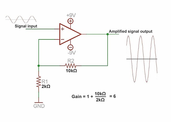
An amplifier is a device that increases the voltage in a circuit. The simplest type is an operational amplifier, and this video will demonstrate how these devices function and how to implement them in electronic applications. As an example,...
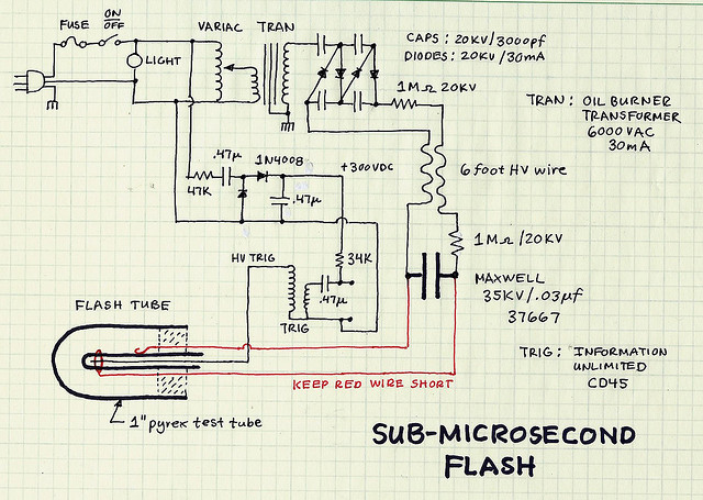
The two resistors serve dual purposes. Firstly, they limit the current to a lower value in case of accidental contact with the circuit. Secondly, when the flash is activated, the main capacitor behaves like a short circuit to the...
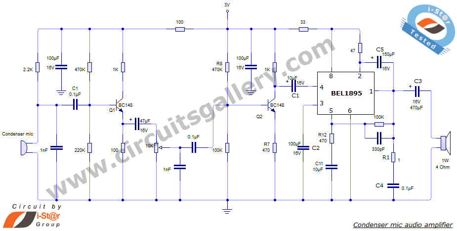
This document presents an audio amplifier circuit suitable for use in walkie-talkies, low-power transmitters, and packet radio receivers. The circuit utilizes a condenser microphone audio amplifier that delivers high-quality audio output of 0.5 watts at 3 volts. The design...
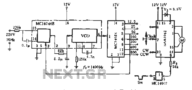
A typical application example is presented, demonstrating the SAA1042 12V stepper motor drive configuration. The phase winding current is set at 200mA. According to RB Figure 5-10, a resistor value of RE = 56kΩ is selected. This resistor is...
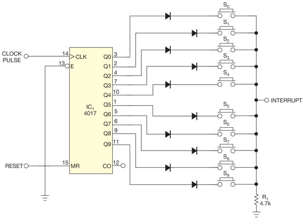
There are several methods to read multiple switch inputs using a reduced number of microcontroller unit (MCU) pins. One approach involves using an analog MCU pin to read multiple switches by assigning a unique voltage to each switch through...