
Converter Circuit 6

The circuit diagram described integrates multiple functionalities, allowing for the processing of RGB signals into color-difference outputs while maintaining high fidelity and stability. The use of LT1398 operational amplifiers ensures low noise and high accuracy in signal processing. The configuration of resistors and diodes allows for precise control over the gain and output characteristics, making this circuit suitable for applications where signal integrity is critical. The design also accommodates the need for dual power supplies, which is common in precision analog circuits, ensuring that the op-amps operate within their optimal voltage ranges.
Moreover, the implementation of stereo surround sound capabilities highlights the versatility of the circuit, enabling it to serve in audio applications as well. The coupling capacitors and variable resistors provide flexibility in tuning the output to match specific audio requirements, while the high output impedance is advantageous for driving subsequent stages without significant signal loss.
In conclusion, this circuit exemplifies a well-thought-out design that effectively addresses the challenges of signal processing in both video and audio domains, making it a valuable component in modern electronic systems.The circuit diagram shows two LT1398`s from Linear Technology used to create buffered color-difference signals from RGB (red-green-blue) inputs. In this application, the R input arrives via 75 coax. It is routed to the non-inverting input of amplifier IC1a and to 1. 07-k resistor, R8. There is also an 80. 6- termination resistor R11, which yields a 75- input impedance at the R input when considered in parallel with R8. R8 connects to the inverting input of a second LT1398 amplifier (IC1b), which also sums the weighted G and B inputs to create a 0. 5Y output. Yet another LT1398 amplifier, IC2a, then takes the 0. 5Y output and amplifies it by a gain of 2, resulting in the +Y output. Amplifier IC1a is configured for a non-inverting gain of 2 with the bottom of the gain resistor R2 tied to the Y output.
The output IC1a thus results in the color-difference output R Y. The B input is similar to the R input. Here, R13 when considered in parallel with R10 yields a 75- input impedance. R10 also connects to the inverting input of ampli er IC1b, adding the B contribution to the Y signal as discussed above The work is easy when a positive input into, The D1, D2 will does not work. The output is equal to R2 / (R2 + R3). When V1 is the input signal and R2 = R3 = R, we will have the output signal V0 = 1 / 2 V1. Later, when the negative output signal into. The D2 to conduct, but D1 does not work. When this circuit is the inverting circuit, output has values V0 = R2/R1 V1, where R1 = 2R, and R2 = R, so V0 = 0.
5 V1. This circuit changes the voltage to current, can provide dc current characteristics and AC so-so Circuit consists of 3 op-amps, 2 transistors is moderate. Passive devices and only a little. This circuit with grounded. load, it controls the rate Vout / Vin easily, it also has a wide area ranging from about 1 uA output rate of resistance to the flow of the output transistor.
It has a high output impedance 50 Meg Ohm is a high accuracy, stability and low noise. The electrical signals from transducer, Sometimes, it is value less too, For input to the circuit to convert signals from analog to digital. To achieve a satisfactory, We need a power amplifier, who can tell strength of the input signal is simple.
This can extend the input signal from the transducer is 10 times and 100 times. Circuit consists of op-amp IC1 No. 741, To give the appearance of non inverting circuit, R1 is configured input impedance switches. In this the 75 kilo ohms, negative feedback circuit consists of R3 or R4 together with R2, which defines the gain of the circuit. Power supply for this circuit requires two sets of power supply positive and negative, which was in the range of positive, negative 6 volts to the positive, negative 15 volts, in this value add, subtract 9, because available with 9-volt battery immediately.
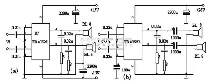
Integrated stereo surround sound will come out similar to the Concert Hall. And a simple circuit. Using the LM1458 IC number to expand the difference of the input signal left (L). It came out as surround sound sure enough. When raising the power and enter the left and right input circuit. The signal on the left (L) to signal coupling through C2 and R1 to enter the pin 5 of IC1 / 1. And signs on the right (R) to signal coupling through R4 to C2 and to the pin 3 of IC1 / 2. Then the amplifier IC1 is the difference. Which the same signal is lost. Balance, but only signals different from the output pin 7 and pin 1. The VR1 / 1 and VR1 / 2 is a control gain of the signal on each side. Then the signal via C3 and C4 are coupling the audio signal and send out better, The output. By the way this output is connected to the headset. Or will be connected to the amplifier at all. This converter may help if just the serial port on a personal computer is free, whereas the printer needs a parallel (Centronics) port. It converts a serial 2400 baud signal into a parallel signal. The TxD line, pin 3, 🔗 External reference
Related Circuits
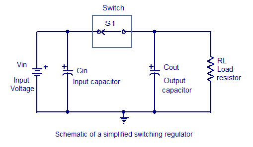
Switching regulators operate by drawing small amounts of energy from the input source and transferring it incrementally to the output. This is achieved using an electronic switch, which functions at a predetermined frequency, acting as a gate between the...
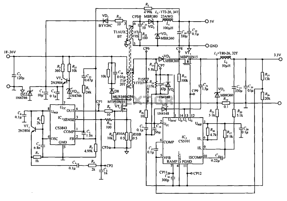
The CS3843 and CS5101 are components of a 5V/3.3V switching DC power supply circuit. The CS3843 is a fixed frequency PWM controller characterized by a set oscillator that precisely controls the duty cycle. It features a temperature-compensated reference voltage,...
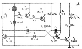
A simple and practical electronic bell circuit can be constructed using the provided schematic diagram. This circuit can function as a doorbell or an alarm system. It utilizes only a few transistors along with several common components. The circuit...
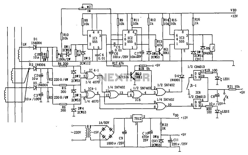
The electrical equipment overload and phase failure protection circuitry includes a +12V and +5V DC power supply, an AC transformer, voltage comparators, timers for blockade, a relay control circuit, and a phase loss protection circuit. The DC power supply...
The TDA1521A amplifier circuit is designed for high-fidelity applications with minimal external components. It is suitable for powering Walkman devices or transforming low-powered computer speakers. The TDA1521A comes in a nine-pin single in-line plastic package and offers output power...
Battery discharge leads to plate acidification, negatively impacting the battery's lifespan. To address this issue, a specialized micro-power battery over-discharge protection circuit has been designed. The circuit features a very low detection current (1.1 mA). Once the protection circuit...