
Few Switching regulator circuits

Switching regulators are essential components in power management applications, providing an efficient means of converting and regulating voltage levels. The operation relies on the principles of energy storage and transfer, where inductors and capacitors work together to minimize ripple and maintain a stable output voltage. The duty cycle, defined as the ratio of the ON time to the total cycle time, is critical in determining the output voltage. By adjusting the duty cycle, the regulator can effectively manage the energy supplied to the load, catering to varying demands.
The inclusion of a Schottky diode in the circuit is particularly advantageous due to its low forward voltage drop and fast switching capabilities, which reduce power losses and improve efficiency. The inductor's role in storing energy during the ON phase and releasing it during the OFF phase is crucial for maintaining output stability. The feedback mechanism involving resistors R1 and R2 ensures that the output voltage remains within the desired range, compensating for any variations in input voltage or load conditions.
The uA78S40's versatility and performance make it suitable for various applications, including battery-powered devices, automotive systems, and industrial equipment, where efficient voltage regulation is paramount. The design of the circuit must consider component ratings and thermal management to ensure reliable operation under varying conditions. Overall, switching regulators like those utilizing the uA78S40 IC play a vital role in modern electronic systems, balancing efficiency, performance, and adaptability.Switching regulators work by drawing small amounts of energy from the input source and transferring it step by step to the output. This task is attained by using an electronic switch (operating at a predetermined frequency) which works like a gate between the input energy source and the output.
This gate controls the amount of charge that is trans ferred to the output load. The output voltage of the switching regulator depends on how much time the switch is maintained closed. If the OFF time of switch is long then less energy will be transferred to the output load and so the average output voltage will a be low.
If the OFF time of switch is short then more energy will be transferred to the output load which results in a better average output voltage. The schematic of a basic switching regulator is shown below. When switch S1 is closed capacitor Cout is charged and when switch S1 is open the Cout discharges through the load.
The duty cycle of the S1 determines how much energy is transferred to the output load. In simple words the capacitor Cout serves as a filter which converts the pulse waveform from the switch in to a steady voltage. The output voltage will be always a function of the input voltage and the duty cycle of the switch. The schematic of a practical switching regulator is shown above. This circuit has two additional components, a Schottky diode D1 and an inductor L1. These two components are present in almost all switching regulator circuits and they drastically improves the performance of the circuit.
Let us see how the diode and inductor improves the performance of the regulator circuit. When switch S1 is closed the inductor L1 opposes the rising current by creating an opposing electromagnetic field and this makes the diode D1 reverse biased and it behaves like an open switch. When switch S1 is made open the electromagnetic field that was induced in the inductor L1 will be discharging and this creates a current in the reverse polarity.
This makes the diode D1 forward biased and it will remain in the conducting stage until the field in the inductor becomes zero. In simple words this action is similar to the charging and discharging of the output capacitor. Thus the combined effect of the inductor and diode improves the filtering capability of the output capacitor and so the circuit efficiency is improved.
Here are two switching voltage regulator circuits using uA78S40 IC from On Semiconductors. The first one is a step down converter while the second one is an inverting converter. uA78S40 is a switching regulator IC that can be used for a variety of applications. The uA78S40 is an integrated switching regulator circuit which has built in circuitries for voltage reference with temperature compensation, oscillator with duty cycle control, high capacity switching element, an independent operational amplifier and independent diode. When voltages excess of 40V or output currents excess of 1. 5A are required external switching transistors must be used. The features of uA78S40 include wide temperature range, adjustable output voltage (from 1. 5V to 40V), peak output current of 1. 5A, 80dB load regulation, 80dB line regulation, wide supply voltage range ( from 2. 5V to 40V), very low standby current etc. The applications of this IC include step up converters, step down converters, inverting converters etc.
The uA78S40 is available in a 16 pin DIP plastic package. The circuit shown above is of a switching step down converter using uA78S40. The input voltage can be 25V DC and the output voltage is 5V @500mA. Ct is the timing capacitor for the internal oscillator while C3 is the input filter capacitor. C3 must be rated above 25V while C2 can be rated anything higher than 10V. The instantaneous output voltage (that is the voltage across output capacitor Cc) is fed back to the inverting input of the internal opamp using the resistor network comprising of R1 and R2. 🔗 External reference
Related Circuits
The circuit below illustrates powering one or two LEDs from the 120-volt AC line using a capacitor to drop the voltage and a small resistor to limit the inrush current. Since the capacitor must pass current in both directions,...
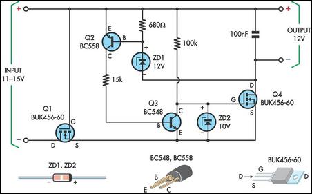
This circuit is designed to power a laptop computer using a solar power setup. The computer requires 12V at 3.3A. The circuit employs a linear regulator with a MOSFET (Q4) as the series pass device. A 100kΩ resistor provides...
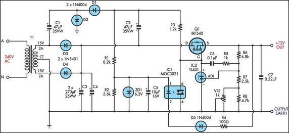
This circuit is a MOSFET-based linear voltage regulator with a voltage drop as low as 60mV at 1A. It utilizes a 15V-0-15V transformer and an IRF540 N-channel MOSFET (Q1) to deliver a regulated 12V output. The required gate drive...
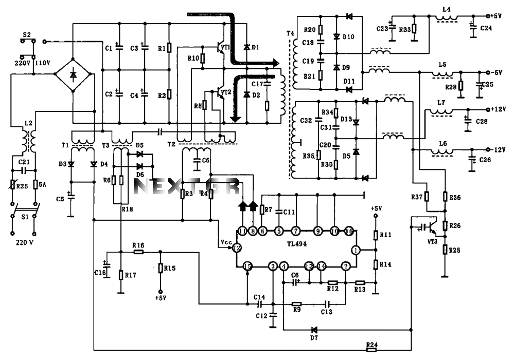
The BE-150 mainframe computer features a switching power supply circuit. The circuit utilizes the oscillation control IC TIA94. A 22V voltage is supplied through the power switch S1, fuse, filter capacitor C21, L2, and a mutual inductance filter, which...
Precision high voltage regulator power supply. Refer to the corresponding page for an explanation of the related circuit diagram for the power supply. This simple switching regulator circuit provides a 5 V output, with the input supplied by a...
An integrated voltage regulator connected in reverse to a mini drill allows for speed adjustment within specific limits, maintaining a constant speed regardless of load. The electronic speed control is achieved through a voltage regulator, which can power motors...