
converter r2elhc600a 10v

to the load since often less than |400A|, even with 1 Power Module only. Primary use is in LHC particle accelerator irradiated locations (redundancy and Radiation tolerant). The converter is water cooled, and is thus ideally suited to situations where air losses must be carefully managed. Designed for underground operation, extensive remote diagnostics have been foreseen to allow efficient monitoring and fault diagnostics without requiring being present locally.
Power part is identified as a 4 quadrant voltage source, even if an internal current source control is required to adequately share output current between power modules. Power Module is actually a high frequency fully bidirectionnal (+/-400A +/-10V) current source (7-8kHz) controlled by a 1kHz bandwidth voltage loop.
One can notice that Power Module is actually a current cource in its structure, even if voltage source capacitors are located in this block for mechanical reasons. Representation below gives a symbolic structure of the power converter, clarifying the cascade loops.
The multiplication of rectifier stages in each output module gives the following advantages: easier design of magnetic parts, lower rating fuse (lower losses) to protect whole Power Converter being short-circuited by a faulty secondary (fuse would immediately blow in case one of the schottky dies, giving the possibility to the whole power converter to reconfigure the current level in other current sources to maintain required voltage level). Redundance operation relies mainly on [+/-400A +/-10V] inner current source reactivity, and strongly depends of the output current level (400A limit), so that load output current is not impacted by the loss of one sub.
Of course a sudden short at the level of the output stage of a sub converter will lead to a converter global fault stop. High precision current control loop is managed by the digital controller called FGC (Function Generator Controller).
This unit includes a high precision Sigma Delta Analog to Digital Converter which digitalize the analog current measurement coming from 2 DCCTs (DC current Transducer). Precision is then directly relying on sensor precision: DCCT, the ADCs, and the algorithm being used for the regulation loop.
Voltage source is then used as a power amplifier, powering the load through a high bandwidth voltage loop (>500Hz). Power Converter is part of magnet protection scheme, even if not directly fully responsible of the monitoring and diagnostic of the superconductive magnet status.
Dedicated systems QPS (Quench Protection System) + PIC (Power Interlock Controller) can interlock Power Converter if magnet safety requires it. Always ensure that external protection system can stop the Power Converter through a safe signal called Fast Abort.
This redundant signal uses 2 paths to interlock and stop the converter and its redundancy is checked each time it acts. It directly acts on AC and DC Contactor bobbin, ensuring their opening as required. Stop powering the load in safe way (handling the magnet energy even when stopping, through dedicated system called crowbar).
This active system combined with the presence of DC-Contactors in the rack provide a safe resistive discharge path for magnet current (energy). The system is based on a 50 mOhms Power Resistance series back-to-back thyristors being fired at a given output voltage (
🔗 External reference
Related Circuits
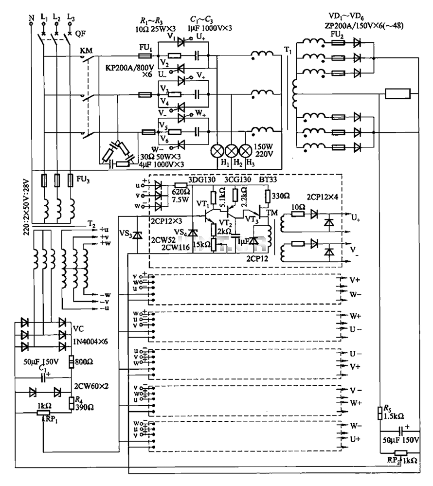
A three-phase thyristor power regulator circuit designed for plating applications, capable of handling currents from 1200A to 6000A at a voltage of 10V. The circuit comprises a main circuit, a trigger circuit, synchronous power components, and a voltage negative...
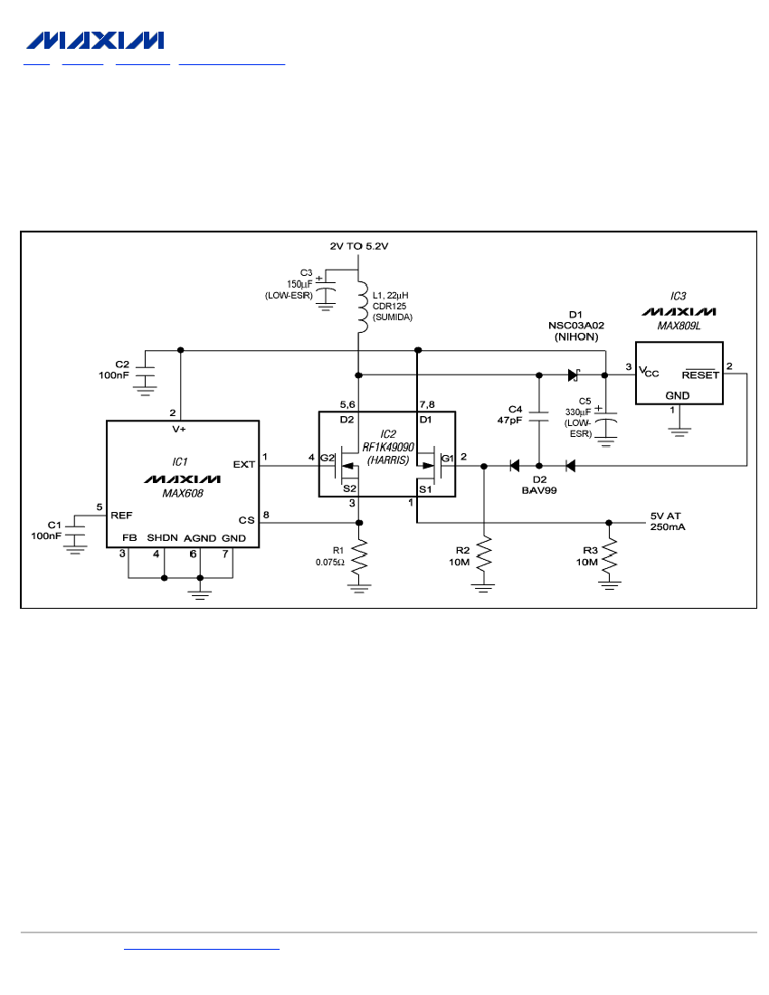
To ensure a full-load start-up, the additional circuitry in this regulated boost converter disconnects the load until the output voltage reaches regulation. Proper operation necessitates a gate-drive voltage adequate to maintain low on-resistance in the switching MOSFET; however, during...
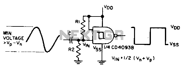
The sine input is AC coupled by capacitor C. Resistors Rl and R2 bias the input midway between Vn and Vp, which are the input threshold voltages. This configuration is designed to provide a square wave at the output. The...
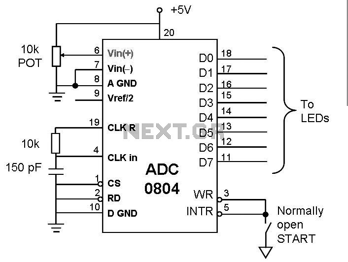
This post discusses the interfacing and operation of Analog-to-Digital Converters (ADCs). An ADC is a device that converts the analog signals from transducers into digital signals, enabling computers to process the data. ADCs are essential for obtaining meaningful results...
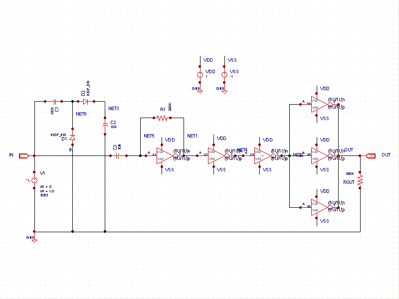
This schematic example demonstrates a sinusoidal voltage input at a frequency of 10 kHz, which is converted to a square wave using an inverter-based circuit. The VDD and VSS rails are connected to +1V and -1V, respectively. The control...
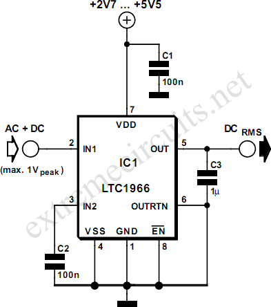
To measure the RMS value of an alternating voltage, an accurate converter is necessary to produce the true RMS value of its alternating input as a DC output. For simple sine-wave inputs, the RMS voltage can be calculated as...