
Coulomb meter

The circuit in question involves an integrated circuit (IC1) whose input current contributes to voltage drift. This phenomenon occurs as the input current gradually charges the capacitor (C1) over time. The charging process of capacitor C1 can lead to an increase in voltage across it, which may affect the overall performance of the circuit, especially when the output voltage is at or near 0 volts.
In practical applications, the behavior of IC1 can be influenced by the characteristics of the capacitor, including its capacitance value and equivalent series resistance (ESR). A capacitor with a higher capacitance may take longer to charge, resulting in a more pronounced voltage drift effect. Conversely, a capacitor with lower ESR can charge more quickly, potentially mitigating the drift.
To analyze this circuit further, it is essential to consider the time constant defined by the product of the resistance in the charging path and the capacitance of C1. This time constant determines how quickly the capacitor charges and can significantly impact the stability of the output voltage. If the time constant is too long, it may lead to instability in applications requiring rapid response times.
In designing circuits where voltage stability is critical, it may be beneficial to implement additional components, such as a feedback mechanism or a voltage regulator, to counteract the effects of the input current on the capacitor. This could help maintain a more stable output voltage across varying conditions and load scenarios.
Furthermore, careful selection of IC1 and C1, along with their respective parameters, can enhance circuit performance and minimize voltage drift, ensuring reliable operation in sensitive electronic applications.Another cause of voltage drift is the input current of IC1, which slowly charges capacitor C1, this can especially be seen when the output voltage is about 0 Volt. 🔗 External reference
Related Circuits
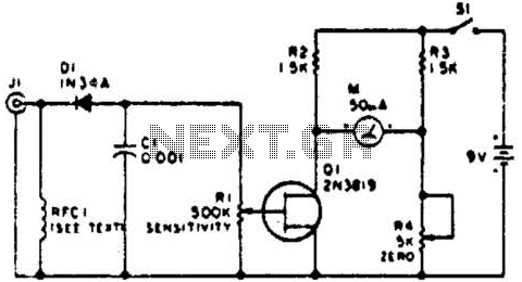
This circuit employs a FET as a DC amplifier within a bridge configuration. Resistor R4 is adjusted for meter nulling with switch J1 short-circuited. Any surplus 50-mA meter can be utilized in this circuit. RFC1 represents a suitable RF...
A signal conditioner for a pH meter probe requires high input impedance. The signal conditioning of the pH meter probe is achieved by incorporating a buffer. The design of a signal conditioner for a pH meter probe is critical for...

The frequency meter described not only serves its primary function but also allows for the measurement of inductance in various coils, resonant frequency of circuits, and capacitance of capacitors. The schematic diagram of this combined device is illustrated in...
Digital Remote Thermometer. The remote sensor transmits data through the mains supply. The temperature range is from 0.0 to 99.9 °C. Transmitter circuit diagram includes the following components: R1, R3 = 100K 1/4W resistors; R2 = 47Ω 1/4W resistor;...
A spectrometer is an instrument used to view and analyze a spectrum of a specific characteristic of a substance, such as mass-to-charge values in mass spectrometry or wavelengths in absorption spectrometry, including techniques like nuclear magnetic resonance spectroscopy and...

The Atmega8 microcontroller from Atmel features numerous digital and analog input/output lines, making it an ideal choice for developing various measurement equipment. It is essential to have the GCC AVR programming environment installed, as outlined in the article "Programming...