
Frequency meter - LC measuring instrument

The error of measurement of frequency does not exceed 5 %. The principle of work of a frequency meter is based on transformation of an entrance signal to sequence of rectangular impulses with stable duration and amplitude and the subsequent measurement by the microampermeter of average value of a current of this sequence. Simply work of a frequency meter explain ‹, given on fig. 3. A studied signal (fig. 3, and) submit on an entrance of buffer knot which is executed on the VT1 transistor. Purpose of knot - to provide big entrance resistance and the minimum entrance capacity of a frequency meter.
From a knot exit the signal arrives through the SA1 switch section SA1. 1 on the converter executed on the elements DD4. 1, DD4. 2. It serves for formation from an entrance signal of any form of sequence of rectangular impulses which from an element DD4. 2 exit (fig. 3, ) arrive or is direct on an inverter entrance on the VT2 transistor (if to establish the first ° ° · ½), or on an entrance of a divider of frequency (at work on others ° ° · ½ ° …), executed on DD1 counters - DD3.
Each of counters divides frequency of an entrance signal on 10 therefore irrespective of the fact which it is established ° ° · ½, frequency of sequence of impulses on an entrance of the transistor inverter will be no more than 500 Hz. On the DD4. 3 inverter and the element DD4. 4 the shaper stable on amplitude and duration of impulses is executed. Tension of high level from a VT2 transistor collector (fig. 3, in) arrives on an entrance of the DD4. 3 inverter and on integrating chain of R8 R9 C6. On top according to the circuit an entrance of the element DD4. 4 tension of low level (fig. 3, g), and on its bottom entrance - high (fig. 3, ), but with a temporary delay which depends on a sign of a constant of time of an integrating chain is established.
Duration of a delay regulate the tuning R8 resistor, and its value defines duration of impulses of t on an element DD4. 4 exit (fig. 3, µ). Average value of a current of sequence of these impulses measure by means of the PA1 microampermeter.
Value of a current proportionally to frequency of an entrance signal. And how the inductance measuring instrument works For this mode the SA1 switch transfer to situation "L". The converter on the elements DD4. 1, DD4. 2 turns into the generator which frequency is defined by value of capacity of the C2 condenser and inductance of the L … coil - it connect to nests ¥2, ¥3.
Value of frequency measure by a frequency meter (its work is described above), and inductance calculate on a formula: L … = 1/fU2, where L … - in ½, a f - in MHz. For convenience of counting a scale of the device it is possible in addition ³ ° ƒ ² ° ‚ in values of inductance or to make separately for ever
🔗 External reference
Related Circuits
Ultrasonic cleaning primarily relies on the phenomenon of ultrasonic cavitation. In the presence of a sound field, liquid bubbles undergo high-frequency micro-vibrations. When the sound pressure reaches a specific threshold, air bubbles grow rapidly and then collapse suddenly, creating...
The Digital Thermometer 0-100 °C is a device designed for temperature measurement in Celsius. It utilizes a microcontroller AT89C4051 as its data processor. The temperature sensor employed in this thermometer is the LM35D, which provides accurate temperature readings. The...
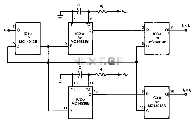
The circuit can be used to determine whether an input signal falls within a specific frequency range. The device comprises three integrated circuits (ICs), including a dual monostable multivibrator and two dual D-type flip-flops. The signal whose frequency is...
This is a simple 3-digit digital voltmeter. A PIC16F676 microcontroller is utilized to read analog signals (voltage) and display the value on a 3-digit 7-segment display. Similar principles can be applied to measure DC current using a parallel resistor...
This simple-to-construct water fishing thermometer circuit is intended for use in sports applications, such as fishing contests. A sensor measures... This water fishing thermometer circuit is designed to provide accurate temperature readings of water, making it an essential tool for...
This circuit is a frequency meter, low cost. It covers region 1HZ until 1MHZ. The IC1 schmitt trigger that it regulates the signal of entry and him changes in reasonable level suitable for the IC2-3-4. With the tenth pulse...