
CPU number of liquid crystal display driver circuit example tube

Liquid crystal display (LCD) drive circuits play a critical role in controlling the operation of LCD panels, which are widely used in various electronic devices. These circuits typically consist of a combination of integrated circuits (ICs), passive components, and sometimes microcontrollers, which work together to manage the voltage and timing necessary for the proper functioning of the LCD.
The primary function of an LCD drive circuit is to generate the necessary waveforms that control the alignment of liquid crystal molecules in the display. This is achieved through a series of voltage levels applied to the electrodes of the LCD. The drive circuit must be capable of producing different waveforms for different pixel states, ensuring that the display can represent various images and text clearly.
In a typical LCD drive circuit, a microcontroller or dedicated LCD controller IC interfaces with the CPU to receive image data. This data is processed and converted into specific control signals that determine the on/off state of individual pixels. The drive circuit may include components such as resistors, capacitors, and transistors to shape the output signals and manage the timing for refreshing the display.
Moreover, the design of the LCD drive circuit can vary depending on the type of LCD technology used, such as twisted nematic (TN), in-plane switching (IPS), or organic light-emitting diode (OLED). Each technology may require different driving voltages and signal timings, which must be accounted for in the circuit design.
In summary, the structure of an LCD drive circuit is essential for the effective operation of liquid crystal displays. It integrates various components to ensure precise control over the display's performance, enabling high-quality visual output in electronic devices.Examples of the structure of a number of liquid crystal display drive circuit CPU tubes.
Related Circuits
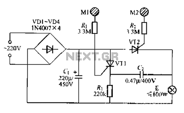
A circuit configuration features a relatively new strong key touch-state switch. Normally, the thyristors VT1 and VT2 are in the off-state, allowing minimal current to pass through the lamp F. At this point, the capacitance C comes into play....
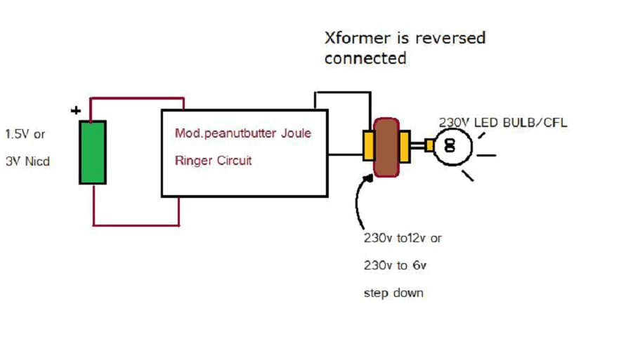
Various threads on ringer circuits have been observed, showcasing multiple variants, particularly concerning the types of transformers utilized, such as air core and step-down transformers. One notable circuit is the 12V-to-120V configuration, which employs a joule ringer that utilizes...
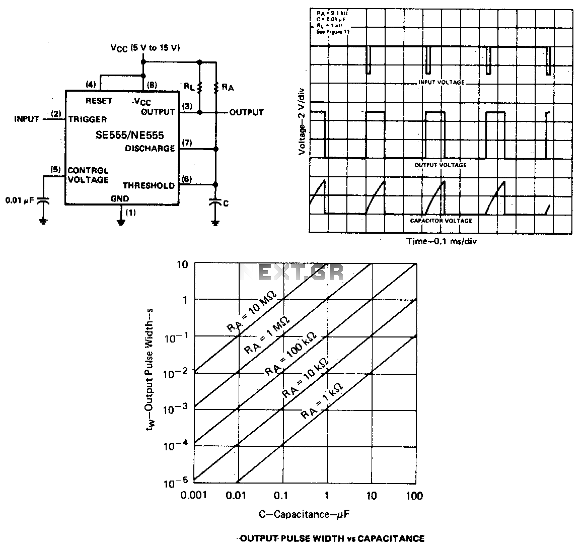
When the output is low, applying a negative-going pulse to the trigger input sets the flip-flop (Q goes low), driving the output high and turning off component 1. Capacitor C is then charged through resistor Ra until the voltage...
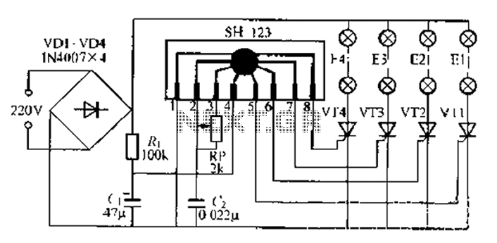
A water Happy Valley-type four flashing lights string controller, electric bollard is designed for use with a type J Ding Japanese lantern. The circuit employs a specific integrated circuit (IC) utilizing CMOS technology. It features a black soft cream...
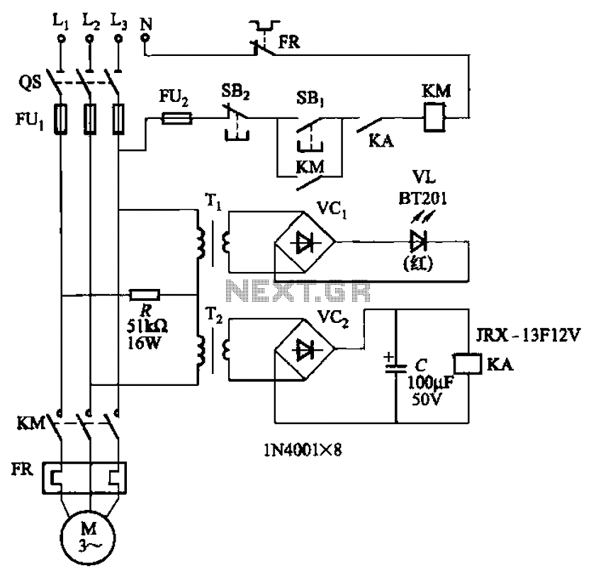
The circuit depicted in Figure 3-92 employs a dual-phase sequence protection relay for sensing. When the power supply exhibits a positive phase sequence (U, V, W), the relay KA is activated. If the power supply maintains the correct phase...
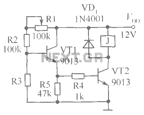
This document presents a brightness control relay circuit. Resistors R1, R2, and R3 create a voltage divider circuit with a light-sensitive resistor. When the light level drops below a specific threshold, the base voltage of VT1 increases, causing VT1...