
Circuit diagram of brightness control relay

The brightness control relay circuit is designed to automate the activation of devices based on ambient light conditions. The core of the circuit consists of a voltage divider formed by resistors R1, R2, and R3, in conjunction with a light-sensitive resistor (often a photoresistor). This configuration allows the circuit to monitor the intensity of light in the environment.
When the ambient light decreases to a predetermined level, the voltage at the base of transistor VT1 rises. This increase in voltage is crucial as it enables VT1 to turn on, which in turn activates VT2. The conduction of these transistors allows current to flow through the relay coil, energizing the relay and closing the contacts, which can be used to control various electrical devices such as lights or fans.
Resistor R1 plays an important role in setting the sensitivity of the circuit. By adjusting R1, the user can modify the threshold at which the circuit responds to changes in light levels. This feature is particularly useful in applications where varying light conditions are present, allowing for fine-tuning of the system's response.
It is essential to note that the performance of the light-triggering mechanism is influenced by both the supply voltage and the ambient temperature. Fluctuations in supply voltage can affect the operation of the transistors and the relay, while temperature changes can alter the resistance of the light-sensitive resistor, impacting the overall sensitivity and reliability of the circuit.
In summary, this brightness control relay circuit is a practical solution for automatic control of devices based on light intensity, with adjustable sensitivity and considerations for external factors such as supply voltage and temperature.Shown for the brightness control relay circuit. Resistors R1, R2 and R3 form a light-sensitive resistor voltage divider circuit, when the light is dark to a certain extent, VT1 base voltage rises to make VT1, VT2 conduction, the relay pull-J. R1 is used to adjust the motion sensitivity. The light trigger level circuit greatly influenced by the supply voltage and ambient temperature.
Related Circuits
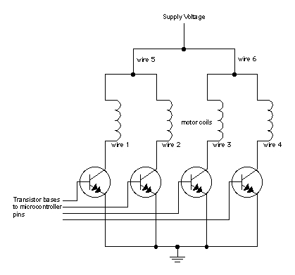
When moving objects with microcontrollers, three types of motors are particularly useful: DC motors, servomotors, and stepper motors. Most motors operate on the electrical principle of induction. When electric current flows through a wire, it generates a magnetic field...

The circuit is a high-power car audio amplifier schematic. It functions as a car audio amplifier using the PA02 and LH0101 integrated circuits (ICs). Each IC delivers an output power of 30W with an 8-ohm impedance. The part list...
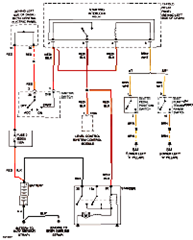
This circuit below shows an electrical circuit applicable for the Audi A4 Quattro 2004 model year. Component: Transmission, Anti-lock Brakes Circuit. The electrical circuit for the Audi A4 Quattro 2004 model year encompasses critical components such as the transmission system...
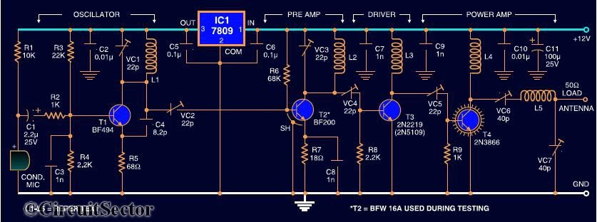
Here is the circuit diagram of a four RF stage FM transmitter. The stages include a very high frequency (VHF) oscillator built around the HF transistor BF494, a pre-amplifier using the BF200 transistor, a driver transistor 2N2219, and a...
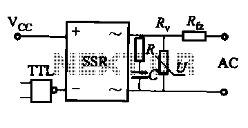
This document discusses the AC solid-state relay (AC-SSR) and presents its basic application circuit as illustrated in Figure (a). Additionally, it includes a TTL drive SSR circuit depicted in Figure (b), a CMOS driver circuit for the SSR shown...

The static display circuit is illustrated in Figure 6. The 74LS244 acts as bus drivers, and six figures represent a public bus, each equipped with an LED display latch (like the 74LS273) connected to the code for latching the...