
Creating Buffer front end circuit to read AD744

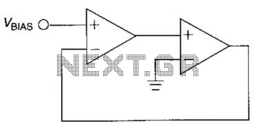
The circuit described involves an AD744 operational amplifier, which is configured to output a voltage signal. The output of the AD744 is coupled through a 10nF capacitor, which serves to block any DC component of the signal while allowing AC signals to pass. This capacitor also plays a role in filtering, potentially smoothing the output signal before it is processed further.
After the capacitor, a 1kΩ resistor is connected to ground. This resistor forms a voltage divider with the capacitor, influencing the time constant of the circuit and affecting the response time of the signal at the junction between the capacitor and the resistor. The combination of the capacitor and the resistor creates a low-pass filter that determines the frequency response of the output signal.
At the junction where the capacitor and the 1kΩ resistor meet, a 4.7kΩ resistor is connected to the test point. This resistor serves to provide a load to the circuit and can also be part of a further signal conditioning stage. The value of the 4.7kΩ resistor suggests that it is designed to allow for a specific voltage drop at the test point, which can be measured for further analysis or testing purposes.
Overall, this circuit configuration is commonly used in signal processing applications where it is crucial to filter out noise and ensure that only the desired frequency components of the signal are passed to the test point for measurement or further processing. The choice of resistor and capacitor values indicates a careful design consideration for achieving the desired electrical characteristics and performance of the circuit.Before the test point there is an AD744 with its output connected to a 10nF capacitor and after there is 1K resistor that goes to GND, from this node of connection of capacitor/resistor there is a 4. 7k resistor that goes to the TEST POINT. 🔗 External reference
Related Circuits
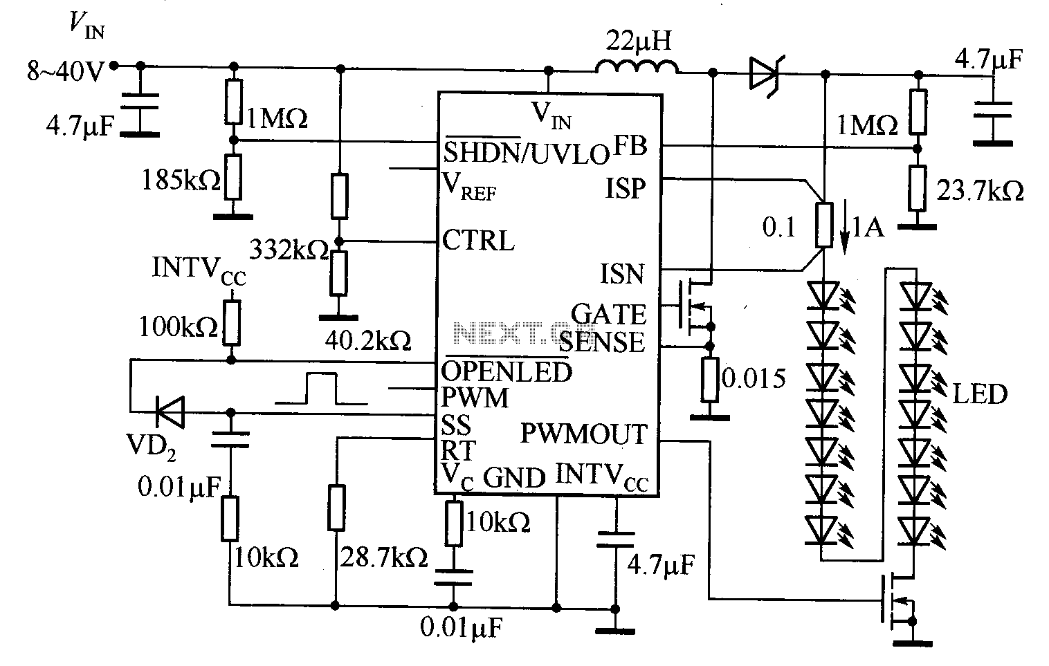
The LT3755 is utilized for high-side current sensing in LED strings, enabling flexible programming and control. It supports a PWM input that allows for a dimming ratio of up to 3000:1, while the CTRL input offers additional analog dimming...
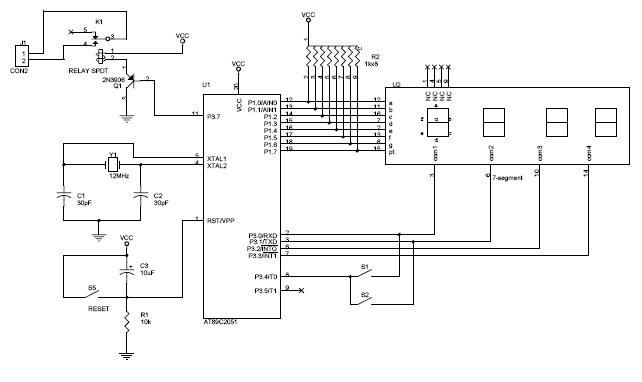
This circuit measures the distance covered during a walk. The hardware is housed in a small box that can be placed in a pocket, and the display is designed as follows: the leftmost display D2 (the most significant digit)...
A series of shunts and multipliers selected by a switch can be utilized in conjunction with a single basic meter to create a multirange instrument, commonly referred to as a multimeter. This device is capable of measuring voltage, current,...
The circuit diagram above illustrates the Clock Controller V1.1. Pins P3.0 to P3.3 are connected to the base of a 4-PNP transistor, specifically the 2N2907, which is used to sink current. The Clock Controller V1.1 circuit is designed to manage...
The output frequency of this simple, low-cost active voltage-controlled oscillator circuit is based on the inherent frequency-dependent characteristics of an operational amplifier. The oscillator circuit utilizes a TL082 op-amp. Upon application of power, the circuit generates a sinusoidal wave....
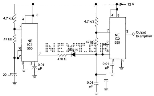
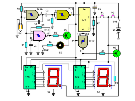
IC1 generates a pulse that modulates the 1000-Hz tone generated by IC2. This circuit can be used to generate warning or alert signals. The circuit described consists of two integrated circuits (ICs), where IC1 is responsible for generating a pulse...