
CRT and Power Supply for Oscilloscope

The circuit design described focuses on the high voltage section of a cathode-ray tube (CRT) oscilloscope, which remains consistent with traditional vacuum tube technology. The CRT requires effective shielding from electromagnetic interference, particularly from the 60Hz magnetic fields generated by nearby power transformers. Standard cold roll steel has proven insufficient for this purpose, as it does not provide adequate attenuation of the magnetic field.
To address this issue, the use of mu-metal is recommended. Mu-metal is a nickel-iron alloy known for its exceptional magnetic shielding properties, offering 100 to 1000 times the effectiveness of steel. It is available in foil form, allowing for easy application around the CRT to enhance its performance and reduce interference from external magnetic fields.
Furthermore, the design suggests the implementation of high voltage transformerless switching regulators, such as TOPSWITCH devices. This approach aims to eliminate the need for traditional vacuum tube diodes and the bulky main transformer, thereby streamlining the circuit and potentially improving efficiency. The adoption of switching regulators can lead to a more compact and lightweight design, which is advantageous in modern electronic applications. This transition reflects a broader trend in electronics towards more efficient power management solutions, enhancing the overall performance and reliability of the oscilloscope.The high voltage section of the CRT is unchanged from the original vacuum tube oscilloscope used as the basis of this design. The CRT requires shielding from the main power transformer. Cold roll steel around the CRT does not provide enough shielding from the 60Hz magnetic field. There are certain nickel alloys, such as mu-metal, that provide 100 to 1000 times the magnetic shielding as steel.
Mu-metal can be purchased in a foil that can be wrapped around the CRT. A design using high voltage transformerless switching regulators (TOPSWITCH, etc.) should be considered to eliminate the vacuum tube diodes and the main (heavy) transformer in this circuit. 🔗 External reference
Related Circuits
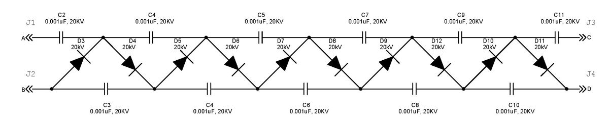
The Cockcroft-Walton multiplier employs a series of diodes and capacitors arranged in a cascade to generate a high-voltage DC potential from an AC input. This circuit topology utilizes diodes to charge capacitors in parallel and discharge them in series....
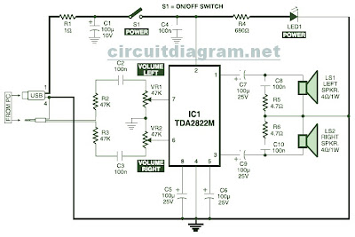
This is the circuit diagram of a USB-powered computer speaker, commonly referred to as multimedia speakers for PCs. The circuit features a single-chip design, operates on a low-voltage electrical power supply, is compatible with USB power from computers, includes...
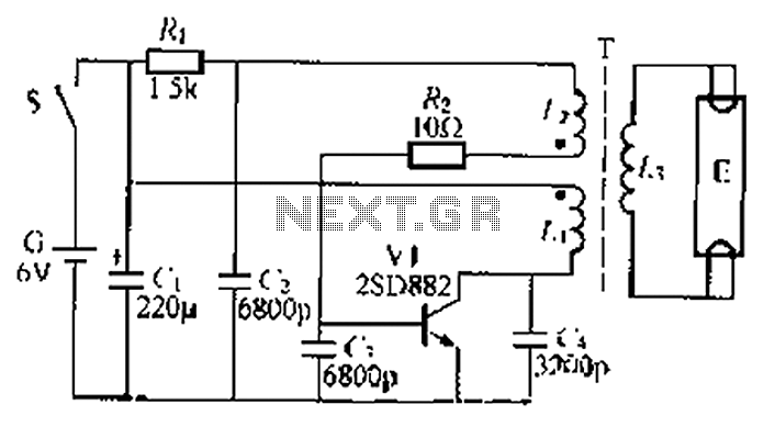
The circuit described is a battery-powered fluorescent lamp system designed for temporary emergency lighting during power outages. It utilizes a transistor (V7) and a boosting transformer (T) along with an inductive feedback oscillator to generate a high-voltage output. When...
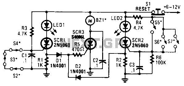
In this circuit, a low-powered silicon-controlled rectifier (SCR) is utilized to trigger a higher-powered SCR. When a switch is opened (S2, S3, S4) or closed (S5, S6, S7), either SCR1 or SCR2 is activated. This action subsequently triggers SCR3...

In many oscilloscopes, the most sensitive range is between 2 to 5 mV, although it is often possible to improve this to 1 to 2 mV by using a variable gain control. To achieve even better sensitivity, the current...
The LM317 is capable of providing extremely good load regulation, but a few precautions are needed to obtain maximum performance. For best performance, the programming resistor (R1) should be connected as close to the regulator as possible to minimize...