
Stereo PC Speaker Powered USB Speaker Schematic Diagram

The USB-powered computer speaker circuit is designed to provide a compact and efficient audio amplification solution for personal computers. The TDA2822M IC is a robust choice for this application due to its ability to deliver substantial audio output while maintaining low power consumption. The implementation of a Zobel network using resistors and capacitors helps to stabilize the amplifier and improve the frequency response, minimizing potential distortion at higher frequencies.
The choice of a USB power source not only simplifies the power supply requirements but also enhances the portability of the speaker system, making it suitable for various applications, including portable audio setups. The inclusion of individual volume controls for each channel allows for precise audio management, catering to user preferences for sound balance.
When designing the PCB layout, it is crucial to ensure that the traces carrying audio signals are kept short and away from power supply traces to minimize noise interference. Additionally, proper heat dissipation measures should be taken into account, especially if the amplifier is expected to operate at higher volumes for extended periods. The use of a socket for the TDA2822M allows for easy replacement or upgrading of the IC, enhancing the longevity and versatility of the speaker system.
Overall, this circuit represents an effective solution for users seeking a simple yet high-performance multimedia speaker system powered directly from a USB port, making it ideal for use with laptops, desktops, and other USB-enabled devices.This is the circuit diagram of USB powered computer speaker, or it widely known as multimedia speakers for PCs. The circuit has single-chipbased design, low-voltage electrical power supply, compatibility with USB power from computer, simple heat-sinking, inexpensive, large flexibility and wide temperature tolerance.
At the heart of the circuit is IC TDA2822M. This IC is, actually, monolithic type in 8-lead mini DIP (Dual Inline Package). It`s designed for use as a dual audio power amplifier in battery powered sound players. Features of TDA2822M are very low quiescent current, low crossover distortion, DC source voltage down to 1. 8 volts and minimal output power of approximately 450 mW/channel with 4 ohm loudspeaker at 5V DC supply input.
An ideal power amplifier can be basically described as a circuit which can supply audio power into external loads without having producing substantial signal distortion and without having consuming extreme quiescent current. This circuit is powered by 5V DC source obtainable from the USB port of the Computer. When electrical power switch S1 is turned to on` position, 5V power supply is extended towards the circuit and power indicator red LED1 illuminates immediately.
Resistor R1 is actually a current surge limiter and capacitors C1 and C4 work as buffers. The operation of the circuit is very simple. Audio signals from the Computer audio port or headphone port are fed towards the amplifier circuit via R2 and C2 (for left channel), and R3 and C3 ( forright channel). Potensiometer VR1 used as the volume controller for left (L) channel, while potensiometer VR2 used to control the volume level of right (R) channel.
Pin 7 of TDA2822M receives the left channel sound signals and pin 6 receives the right channel signals by way of VR1 and VR2, correspondingly. Amplified signals for driving the left and right loudspeakers can be obtained at pins 1 and pin 3 of IC1, correspondingly.
Components R5 and C8, and R6 and C10 form the classic zobel network. Construct the circuit on a medium size, general purpose PCB and enclose inside a appropriate case. It really is recommended to utilize a socket for IC TDA2822M. The external connections ought to be made working with suitably screened wires for improved result. 🔗 External reference
Related Circuits

Often, there is a need for an additional telephone ringer in an adjoining room to be alerted about incoming calls. For instance, if the telephone is situated in the drawing room, an extra ringer may be required in the...
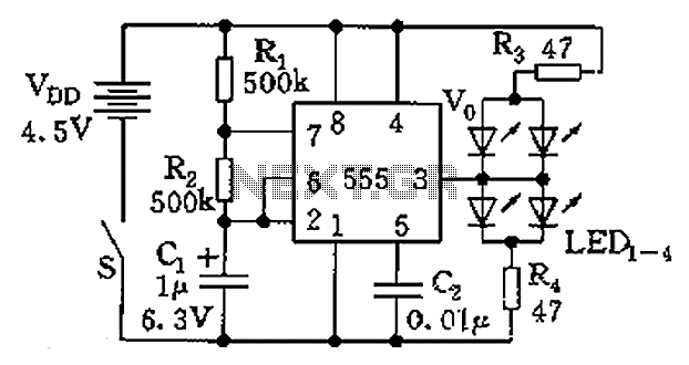
The circuit consists of a 555 timer and a light-emitting diode (LED) array. The 555 timer, along with resistors R1, R2, and capacitor C1, forms an astable multivibrator configuration. The oscillation frequency is calculated using the formula f =...
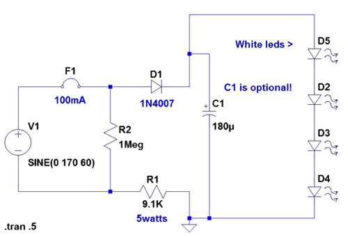
If the AC supply is 220 volts, which resistor should be replaced and with which one? Since 220V is twice that of 110V, the resistance value needs to be doubled accordingly. It is suggested to replace the 9.1kΩ resistor...
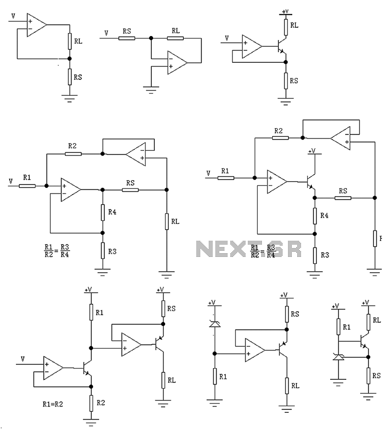
The circuit is designed to provide several constant current outputs to the load resistor RL. The first RL is floating and is rarely utilized. The second RL serves as a virtual ground and is not commonly used either. The...
I like to see lights move to music. This project will indicate the volume level of the audio going to your speakers by lighting up LEDS. The LEDS can be any color so mix them up and really make...
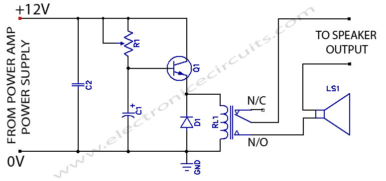
When powering on a power amplifier, a loud thump sound occurs due to a sudden heavy discharge current through the speaker. This current has the potential to damage the speaker, particularly in the case of a direct-coupled amplifier. The phenomenon...