
cruddy v 2 line follower mobile robot

The Cruddy version 2 robot operates as a line-following device, employing a series of digital logic gates to process input signals from sensors that detect the line on the ground. The design typically includes two main components: the sensor array and the logic circuit.
The sensor array is composed of infrared (IR) sensors that continuously monitor the surface beneath the robot. When the sensors detect a change in reflectivity—indicating the presence of a line—the output signal is directed to the digital logic gates. The gates are configured to interpret these signals and control the motors that drive the robot's wheels.
The logic circuit may consist of various gates such as AND, OR, and NOT gates, which work together to create a control logic that determines the movement of the robot. For example, if the left sensor detects the line, the logic circuit can be designed to stop the left motor while allowing the right motor to continue, thus steering the robot back onto the line.
The absence of a microcontroller simplifies the design and reduces costs, making it an excellent educational project for understanding the fundamentals of digital electronics and robotics. Furthermore, the aesthetic enhancements contribute to the robot's appeal, showcasing how functional design can merge with visual creativity in electronic projects.
Overall, the Cruddy version 2 robot exemplifies a practical application of digital logic in robotics, illustrating the principles of sensor integration and motor control without the complexity of programmable components.This is my 5th robot. He is Cruddy version 2. Still he is a line following robot but has now abetter circuit design (originally designed by me) and has cool appearance :D This project doesn`t have any microcontroller. It is designed through digital logic gates only. I used two.. 🔗 External reference
Related Circuits
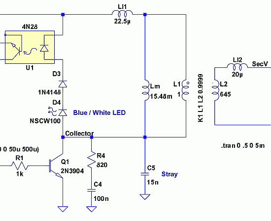
Since then, NL has evolved into the Microsoft Windows®-based NL4, which has been extensively used by world-class engineers in various fields of electronics for almost 10 years. NL5 is the first version to be publicly available. Unlike conventional SPICE-based...
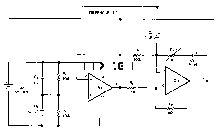
This circuit is a bidirectional amplifier capable of amplifying both signals in a duplex telephone conversation. It operates on the principle of negative resistance. While such an amplifier may be prone to instability, adjusting the load resistor (Rl) can...
Most mobile chargers lack current and voltage regulation, as well as short-circuit protection. These chargers typically provide unregulated 6-12V DC for charging battery packs, which generally have a rating of 3.6V and 650mAh. To enhance battery life, it is...
With this simple project, you can have balanced lines too, simply adapting the unbalanced inputs and outputs of your hi-fi gear to become balanced, and then back to unbalanced at the other end. You can even be extra cunning,...
The drawings and photos below are for an operating incline railway that was built by the London Model Railroad Group for its O scale model railway club located at London, Ontario, Canada. This is a single car model loosely...
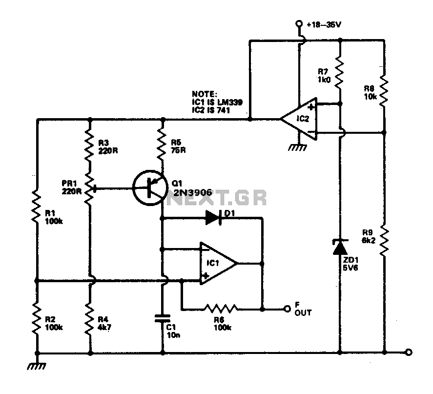
This circuit provides a linear frequency increase of 10 Hz per °C over a temperature range of 0 to 100 °C and can be utilized with logic systems, including microprocessors. The temperature probe Q1, utilizing the Vbe characteristic, changes...