
crystal base oscillator circuit

The circuit utilizes a 3.5795 MHz crystal oscillator, which provides a stable frequency source. The CD4060 IC serves as both the oscillator and frequency divider, allowing for an efficient means of generating a lower frequency signal from the high-frequency crystal. The operation begins with the crystal oscillating at its fundamental frequency, which is then fed into the CD4060. The internal divider of the CD4060 reduces the frequency by a factor of 512, producing a signal at approximately 6.976 kHz.
Following this, the output from the CD4060 is connected to the CD4017 decade counter, which further divides the frequency by 7. The CD4017 is a popular decade counter that can drive ten outputs in sequence. Once the Q7 output of the CD4017 goes high, it triggers a reset, ensuring that the division process is cyclical and controlled. The result of these divisions is a frequency output of about 998.8 Hz.
To achieve an exact 1 kHz output, a trimmer capacitor (VC1) is incorporated into the circuit. This allows for fine-tuning of the output frequency, accommodating any variations in the crystal frequency or component tolerances. Once the 1 kHz signal is established, it can be further processed through additional decade counters for generating various time periods, making this circuit versatile for applications requiring precise timing signals.
The schematic representation of this circuit would include connections from the crystal to the CD4060, followed by the output leading to the CD4017. The trimmer capacitor would be shown connected to the output stage, allowing for frequency adjustments. Proper power supply connections and grounding must also be indicated to ensure the circuit operates reliably. Overall, this design provides a robust solution for generating accurate time-base signals suitable for a variety of electronic applications.This is circuit for accurate time-base generation using the readily available 3. 5795MHz crystal commonly used in telecommunication equipment. Crystal-based oscillator with divider IC chain or a similar circuit in the form of an ASIC is used for time-base generation. The 3. 5795MHz crystal is used in conjunction with a CD4060-based crystal oscillato r- cum-divider (IC1). The crystal frequency is divided by 512 by IC1, which is further divided by 7 by CD4017 (IC2). IC2 is reset as soon as its Q7 output goes high. Thus the crystal frequency is divided by 3584, giving the final output frequency of around 998. 8 Hz. This frequency can be trimmed to exactly 1 kHz with the help of trimmer capacitor VC1 as shown in the figure. The 1kHz signal can be further divided using decade counters to generate the required time period. EFY lab note. 🔗 External reference
Related Circuits
After conducting experiments with a rotary encoder connected directly to keyboard switches, it was found that the keyboard controller IC (an Intel P8049AH in this case) is unable to detect pulses that are too narrow. Testing involved rotating the...
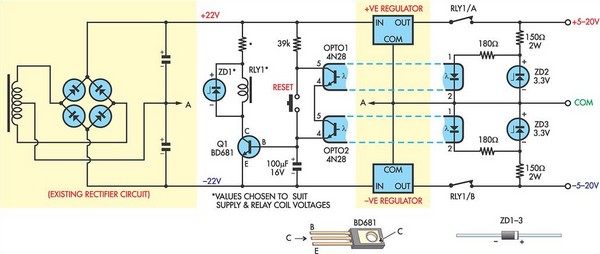
This circuit was designed to protect a dual rail power supply from shorts across the two rails. It uses an optocoupler to monitor each supply rail, with the internal LEDs powered from ZD2 and ZD3 and the associated resistors....
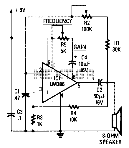
The circuit's frequency of oscillation is given by the formula: f = 2.8 / [C1 x (R1 + R2)]. By adjusting the potentiometer R2, the output frequency can be varied from 60 Hz to 20 kHz. A portion of...
A marker oscillator can be constructed using an NE555 timer to generate pulses at an audio frequency. This design facilitates the identification of signals amidst interference. The oscillator can utilize a crystal with a frequency ranging from 1 to...
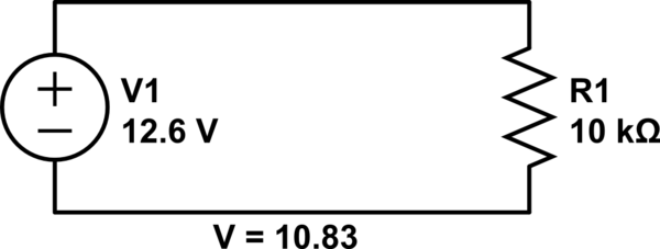
Connect a 12V fan to this circuit that consumes 70mA (0.07A), ensuring the circuit can supply at least that amount of current. There appears to be a misunderstanding regarding the analysis. The voltage drop across the resistor equals the...
An operational amplifier designed for medium power applications, utilized as a headphone amplifier capable of driving low loads. The circuit consists of two amplifiers, with a voltage gain set at 40 dB, determined by the resistor pairs R3-R4 and...