
Zener Tester schematic

More: With the resistors in the circuit selected is the current approximately 1mA, 2mA, 5mA, 10mA and 20mA. Great precision is not necessary. If meter is chosen here a little DVM module. But every other meter can be used if the input resistance but high enough. Construction: The circuit is simple to build on a piece of PCB holes. Note that the DVM module of the circuit a separate isolated power supply needs. Instructions: Connect the test zener diode between the A and K connector. Start with a current of 2mA. This is a safe value for most types of zener diodes. Depending on the type of zener diode, a larger current can be selected. The Zener voltage will vary slightly. Join the zener diode on backwards, the meter will indicate approximately 0.7 V. The same image shows a normal silicon diode. A germanium diode, a voltage of about 0.3 V to 0.4 V, while indicating a Schottky about 0.2 V indicates. Join an LED on A and K, it will light and the V forward (the LED voltage) of the LED indicate. The diode / LED indicates the faulty meter is zero if the voltage on the collector of Q1 is, this is> 25V. Rectifier bridge BR1 = 40V 500mA R1 = 3K3 ¼ W R2 = 5K6 ¼ W R3 = 2k7 ¼ W R4 = 1k ¼ W R5 = 560 ohm ½ W R6 = 270 ohm ½ W C1 = 470?F 35V D1 = 6V2 400mW zener Q1 = BC161-16 S1 = on / off switch S2 = 5 position switch contact a parent ENG = The test diode (Device Under Test) DVM DVM = module Bacon and Dick Best (adjusted to 200V input)
This measuring device is designed to evaluate various types of diodes, including Zener, silicon, germanium, Schottky diodes, and LEDs. The circuit operates by utilizing a transistor (Q1, BC161-16) as a switch, powered by a Zener diode (D1, 6V2) that provides a stable reference voltage to the base of the transistor. The emitter resistor (R2, 5.6kΩ) is selected to allow a current of approximately 1mA to flow through the transistor, ensuring that the circuit operates within safe limits for the tested diodes.
The current through the circuit can be adjusted with the resistors, allowing for various test currents (1mA, 2mA, 5mA, 10mA, and 20mA). The DVM module is used to measure the voltage across the diode under test, with the input resistance of the meter being an essential factor to ensure accurate readings.
The construction involves placing the components on a PCB, ensuring that the DVM module is powered separately to avoid interference. The Zener diode is connected between designated points (A and K), and the measuring process begins with a safe current of 2mA. Depending on the diode type, the voltage readings will differ: for example, a backward-connected Zener diode will show approximately 0.7V, while silicon, germanium, and Schottky diodes will display lower forward voltages.
The circuit also includes a rectifier bridge (BR1, rated for 40V and 500mA) and various resistors (R1, R3, R4, R5, and R6) to ensure proper operation and current limiting. The capacitor (C1, 470µF, 35V) is included to stabilize the power supply. The device's functionality allows for quick testing and identification of faulty diodes, with visual feedback provided by the DVM readings.With this simple measuring device can: Determine the Zener voltage up to 25V. The connections of cathode and anode of each diode finding. Check if a diode fails. Silicon, germanium and Schottky diodes distinguish. LED test and the V forward measure Q1 is connected as power supply. Because D1 is a constant tension on the base and there is resistance in the chosen emitteraansluiting approximately 5.6 V. With an R2 emitter of 5K6 will run through the transistor than 1mA. With the resistors in the circuit selected is the current approximately 1mA, 2mA, 5mA, 10mA and 20mA. Great precision is not necessary. If meter is chosen here a little DVM module. But every other meter can be used if the input resistance but high enough. Construction: The circuit is simple to build on a piece of PCB holes. Note that the DVM module of the circuit a separate isolated power supply needs. Instructions: Connect the test zener diode between the A and K connector. Start with a current of 2mA. This is a safe value for most types of zener diodes. Depending on the type of zener diode, a larger current can be selected. The Zener voltage will vary slightly. Join the zener diode on backwards, the meter will indicate approximately 0.7 V. The same image shows a normal silicon diode. A germanium diode, a voltage of about 0.3 V to 0.4 V, while indicating a Schottky about 0.2 V indicates.
Join an LED on A and K, it will light and the V forward (the LED voltage) of the LED indicate. The diode / LED indicates the faulty meter is zero if the voltage on the collector of Q1 is, this is> 25V. Rectifier bridge BR1 = 40V 500mA R1 = 3K3 ¼ W R2 = 5K6 ¼ W R3 = 2k7 ¼ W R4 = 1k ¼ W R5 = 560 ohm ½ W R6 = 270 ohm ½ W C1 = 470?F 35V D1 = 6V2 400mW zener Q1 = BC161-16 S1 = on / off switch S2 = 5 position switch contact a parent ENG = The test diode (Device Under Test) DVM DVM = module Bacon and Dick Best (adjusted to 200V input)
🔗 External reference
Related Circuits
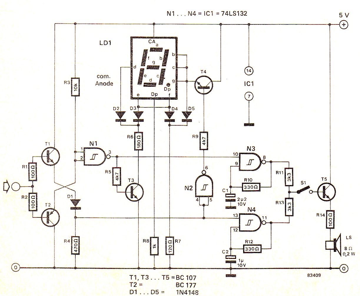
When the input signal is at logic high (1), the display indicates `H`, and the loudspeaker emits a note that is one octave higher than the low tone. The operation of the circuit can be observed in the circuit...

The circuit tests a flyback transformer used in televisions, and it is simple, easy, and inexpensive to construct. A friend who is a TV repairman provided this information. The circuit designed for testing a flyback transformer is essential for diagnosing...
This is a variation of the astable multivibrator. The circuit was recently developed to test N-channel MOSFETs (such as the IRF830). The described circuit is an astable multivibrator configuration tailored specifically for testing N-channel MOSFETs, particularly power MOSFETs like the...
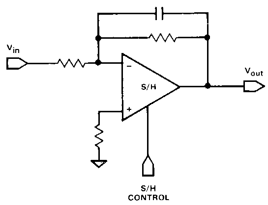
Circuit 1kZ incorporates an operational amplifier (op-amp) component with two inputs, one output, and up and down ports, typically utilized for power supply rails. Additionally, there is a buffer component, which is likely provided by TikZ itself rather than...
Short circuits or broken PCB tracks can be easily identified using a multimeter. However, this tool may yield inaccurate results when assessing the efficiency of a transistor or diode unless the device is unsoldered and removed from the PCB....
This audio amplifier design utilizes two LM3886 chips per channel in a parallel configuration, based on the PA100 parallel amplifier detailed in National Semiconductor's application note AN1192. The amplifier can deliver approximately 50W into an 8-ohm speaker and 100W...