
Crystal Oscillator

The crystal oscillator circuit utilizes the properties of a quartz crystal to generate a stable frequency output. The op-amp serves as the active element that provides the necessary gain and feedback for oscillation. In this configuration, the crystal is connected in a feedback loop with the op-amp, allowing it to determine the oscillation frequency based on its physical characteristics.
The circuit typically includes several key components: the op-amp, the crystal, resistors, and capacitors. The op-amp is configured in a non-inverting amplifier mode to ensure that the output signal is of the same phase as the input, which is critical for maintaining oscillation. The crystal is connected in parallel with a capacitor to form a resonant circuit that defines the frequency of oscillation.
Resistors are used to set the gain of the op-amp and to limit the current through the crystal, protecting it from excessive power that could lead to damage. Additionally, bypass capacitors may be included to stabilize the power supply and reduce noise in the circuit.
The output of the op-amp provides a sinusoidal waveform, which can be further processed or used directly as a clock signal for various applications in digital electronics. The frequency stability and low phase noise characteristics of this oscillator make it suitable for use in communication systems, microcontroller timing applications, and other electronic devices requiring precise frequency generation.
Overall, this low-frequency crystal oscillator circuit exemplifies the practical application of op-amps in generating stable and reliable oscillations, leveraging the inherent properties of quartz crystals.Crystal oscillator, especially the low frequency one, can be easily implemented using op-amp as the amplifier. Here is the schematic diagram of such circuit:.. 🔗 External reference
Related Circuits
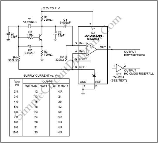
To generate a system clock or auxiliary sleep clock in microcontrollers (µCs) and low-power instruments, a 32 kHz oscillator is commonly utilized. This oscillator typically employs a CMOS inverter. A 32 kHz oscillator is essential for various timing functions in...

Oscillators that generate a predetermined number of pulses are often required in applications such as video work. This oscillator starts 13 ms after the control signal goes high and stops immediately when the input signal goes low. In electronic applications,...
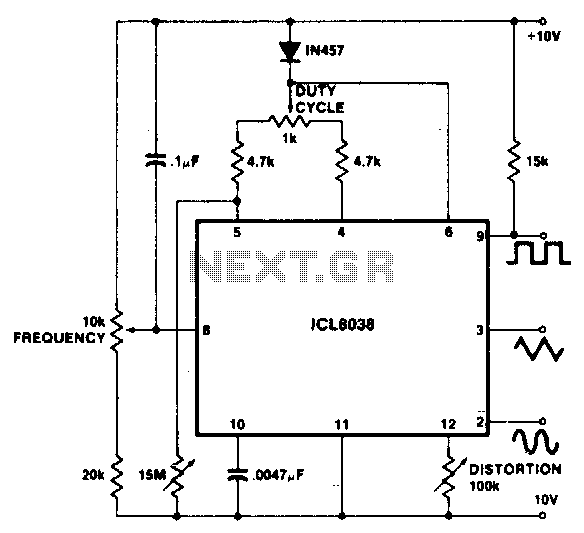
To achieve a 1000:1 sweep range, the voltage across the external resistors Ra and Rb must be reduced to nearly zero. This necessitates that the maximum voltage on control pin 8 surpasses the voltage at the top of Ra...
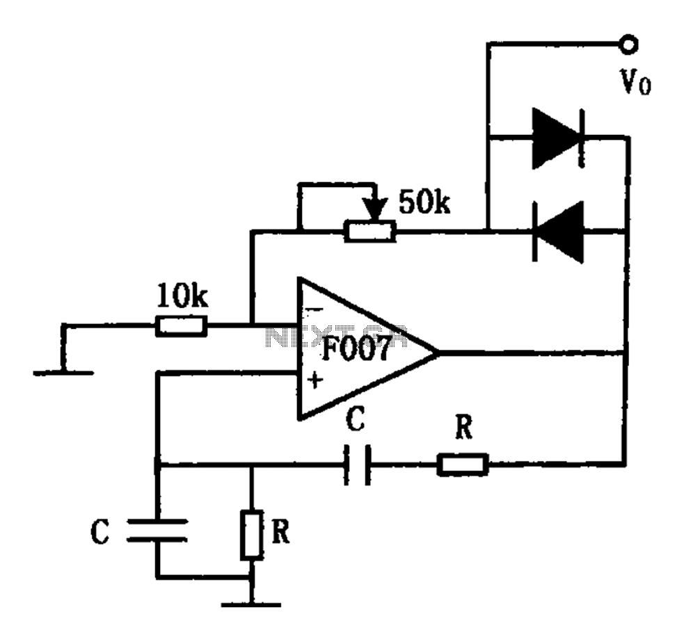
The stable sine wave oscillator circuit is designed to maintain consistent oscillation. The loop gain must be carefully managed; if the gain is excessive, waveform distortion occurs, while insufficient gain can lead to cessation of oscillation. This circuit employs...
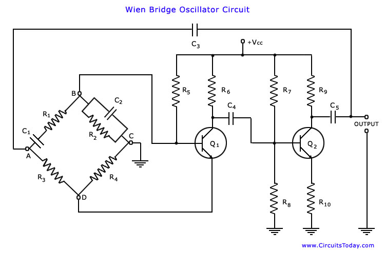
The Wien bridge oscillator is one of the most popular types of oscillators used in audio and sub-audio frequency ranges (20 Hz to 20 kHz). This oscillator features a simple design, compact size, and remarkable stability in frequency output....
The PLL synthesizer oscillator circuit is a feedback loop consisting of a reference oscillator, phase comparator, loop filter, voltage-controlled oscillator, programmable frequency divider, and various other components. In this circuit, the reference oscillator employs a crystal oscillator (OSC) to...