
Stable Start-Stop Oscillator

In electronic applications, pulse generators play a crucial role, particularly in video signal processing and timing applications. The described oscillator is designed to produce a specific number of pulses, which can be essential for synchronizing video signals or creating timing references in various circuits.
The operation of this oscillator is initiated by a control signal. Upon receiving a high-level input, the oscillator begins its cycle after a delay of 13 milliseconds. This delay is critical as it allows for the stabilization of the input signal and ensures that the system is ready to operate without introducing timing errors.
Once the control signal transitions to a high state, the oscillator is activated, and it will generate the predetermined number of output pulses. The precise timing and number of these pulses can be adjusted based on the requirements of the application, allowing for flexibility in design.
When the control signal goes low, the oscillator ceases operation immediately. This feature ensures that the circuit can quickly respond to changes in the input signal, making it suitable for dynamic environments where timing is crucial.
In designing such an oscillator, considerations may include the choice of components such as resistors, capacitors, and integrated circuits that can define the frequency and pulse width. Additionally, the circuit may incorporate feedback mechanisms to improve stability and accuracy in pulse generation.
Overall, this type of oscillator is valuable in various electronic systems, providing reliable pulse generation that meets the demands of modern applications, particularly in the realm of video technology. Oscillators that generate a predetermined number of pulses are often required in applications such as video wo rk. This oscillator starts 13 ms after the control signal goes high and stops immediately when the input signal goes low.
Related Circuits
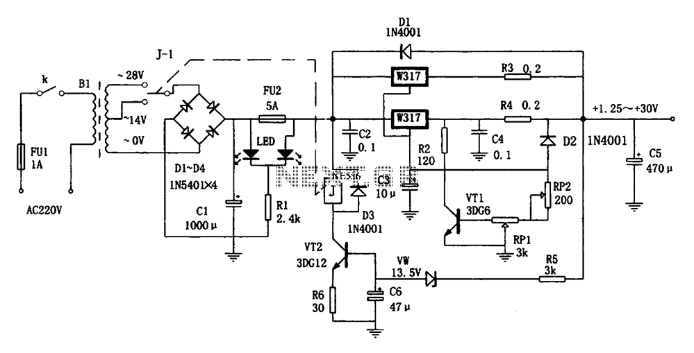
The adaptive adjustable power supply is illustrated in the accompanying figure. The power supply utilizes an LM317 regulator device, and an adaptive switching circuit that automatically adjusts the input voltage based on the output voltage level. This mechanism reduces...
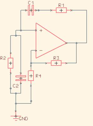
One of the simplest sine wave oscillators is the Wien Bridge Oscillator. Any circuit requires two conditions to oscillate. Tracing the path from the input, through the feedback network, and back to the input, there must be an overall...
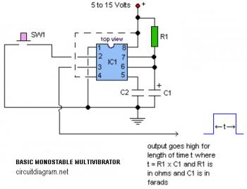
The following circuit illustrates a basic monostable multivibrator, which is based on the 555 Timer IC. Key features include pin 4 functioning as the RESET pin, with the time period defined by the equation t = R1 x C1. The...
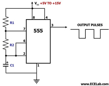
This circuit diagram illustrates the configuration of a 555 timer integrated circuit (IC) as an astable multivibrator. An astable multivibrator is a timing circuit characterized by unstable 'low' and 'high' states. Consequently, the output of an astable multivibrator continuously...
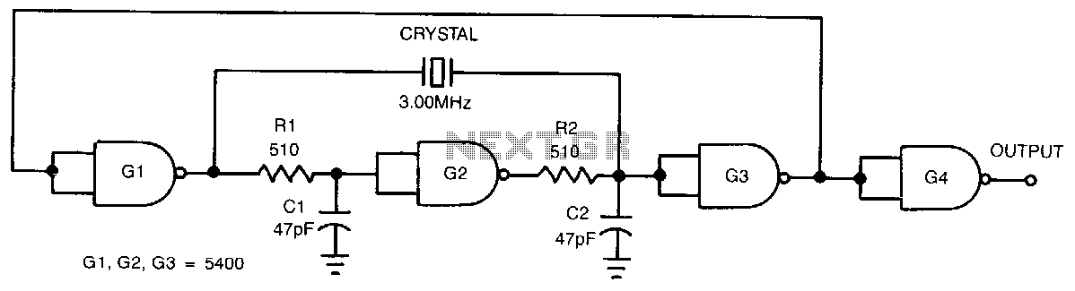
This low-cost, crystal-controlled oscillator employs a single TTL gate. Two key factors facilitate the oscillator's start-up: the configuration of NAND gates G1, G2, and G3 in an unstable logic state, and the high loop gain provided by the three...
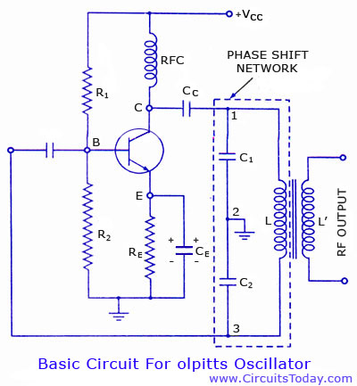
Colpitts oscillator circuit diagram and theory. Colpitts oscillator frequency equation. Colpitts oscillator using transistor. Colpitts oscillator using op-amp. The Colpitts oscillator is a type of electronic oscillator that generates sine waves and is widely used in various applications such as...