
Crystal Oscillator counter

The circuit described utilizes a crystal oscillator to produce a stable frequency, which is essential for accurate timing applications. The choice of a 50 kHz crystal allows for a division to 1 second using a binary counter configuration. The CD4040 counters are employed in a cascaded arrangement to achieve the required division ratio. Specifically, the binary count of 50,000 is reached by combining the outputs of specific bits from the counters, namely bits 15, 14, 9, 8, 6, and 4.
When transitioning to a 100 kHz crystal, the counting scheme shifts, necessitating a rightward movement of the bits in the binary representation to accommodate the increased frequency. This results in a new total of 100,000, derived from the sum of bits 16, 15, 10, 9, 7, and 5.
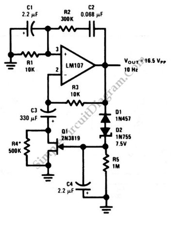
For a 1 MHz crystal, the required resistor values in the oscillator circuit must be adjusted to maintain stability and proper operation. The original 330 kΩ resistor is significantly reduced to approximately 15 kΩ to accommodate the higher frequency. The output from the counters is managed by a Schmitt Trigger inverter, which generates a reset pulse upon reaching the terminal count. This pulse is critical for resetting the counters to zero, ensuring that timing remains accurate.
The timing inaccuracies introduced by the reset pulse width, although minimal, must be acknowledged, especially at higher frequencies where the pulse width approaches the clock cycle duration. The 4040 CMOS counters require a minimum reset pulse width of around 1.5 µs, which places constraints on the design and operation of the circuit. This careful consideration of component values and configurations is essential for achieving the desired accuracy in timing applications.Using a 50 Khz crystal, a count of 50000 is detected when the appropriate counter bits that add up to 50000 are all high. This corresponds to bits 15 (32768) + 14 (16384) + 9 (512) + 8 (256) + 6 (64) + 4 (16). Bits 14 and 15 are the 3rd and 4th stages of the second counter, bit 0 is the first stage of the first counter (Q1, pin 9).
To use a 100 Khz crystal, each bit would be moved one to the right so the total would be (65536 + 32768 + 1024 + 512 + 128 + 32 = 100,000). Using a 1 Mhz crystal, the following bits would be needed: The schematic below illustrates dividing a crystal oscillator signal by the crystal frequency to obtain an accurate (0.01%) 1 second time base. Two cascaded 12 stage counters (CD4040) form a 24 stage binary counter and the appropriate bits are gated together to produce the desired division.
Using a crystal of some even multiple of 2 is desirable so that one stage of the counter automatically toggles every second which eliminates the need for the NAND gate and reset circuitry, however the circuit below illustrates using a crystal which is not an even multiple of 2 and so requires additional components. At 1 Mhz, the 330K resistor in the oscillator circuit will need to be reduced proportionally to about 15K.
When the terminal count is reached, a 7 uS reset pulse is generated by the Schmitt Trigger inverter stage that follows the NAND gate. The 47K resistor and 470 picofarad capacitor sustain the output so that the counters are reliably reset to zero.
This is less than one clock cycle at 50Khz and does not introduce an error but would amount to 7 cycles at 1 MHz which would cause the counters to lose 7 microseconds of time per second. It's not much of an error (7 parts in a million) but it would be there. The minimum reset pulse width for the 4040 CMOS counters is about 1.5 uS, so the reset pulse cannot be made much shorter.
🔗 External reference
Related Circuits
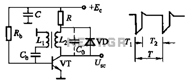
Common non-sinusoidal oscillator circuit, waveform and frequency formula - sawtooth oscillator - use blocking oscillator The sawtooth oscillator is a type of non-sinusoidal oscillator that generates a waveform characterized by a linear rise in voltage followed by a rapid drop....
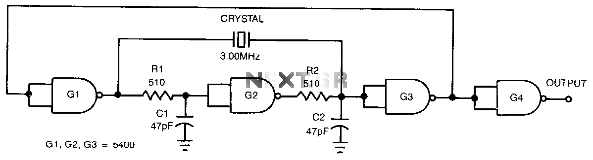
This low-cost, crystal-controlled oscillator employs a single TTL gate. Two key factors facilitate the oscillator's start-up: the configuration of NAND gates G1, G2, and G3 in an unstable logic state, and the high loop gain provided by the three...
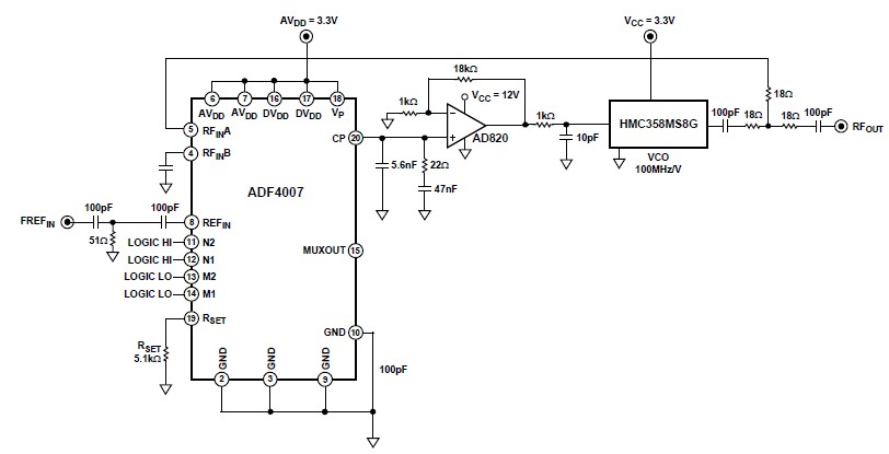
The ADF4007 high-frequency divider Phase-Locked Loop (PLL) synthesizer can be utilized in a variety of communication applications. It operates up to 7.5 GHz on the RF side and 120 MHz at the Phase Frequency Detector (PFD). The device includes...
The 32-kHz low-power clock oscillator provides several advantages compared to traditional oscillator circuits that utilize a CMOS inverter. These inverter circuits often exhibit issues such as significant fluctuations in supply currents across a 3V to 6V supply range, making...
This is a Wien-bridge sine-wave oscillator circuit. This circuit utilizes negative-feedback stabilization to ensure that the gain does not exceed unity. The Wien-bridge oscillator is a type of electronic oscillator that generates sine waves. It consists of an amplifier and...
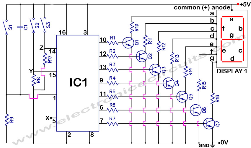
4033 7 Segment Common Anode Display Event Counter Circuit. This circuit can count from 0 to 9 with a reset function and a display test feature. The 4033 7-segment common anode display event counter circuit is designed to count events...