
Common non-sinusoidal oscillator circuit waveform sawtooth oscillator use blocking oscillator

The sawtooth oscillator is a type of non-sinusoidal oscillator that generates a waveform characterized by a linear rise in voltage followed by a rapid drop. This waveform is commonly used in various applications, including signal generation, timing circuits, and audio synthesis. The sawtooth waveform is defined by its frequency and amplitude, which can be calculated using specific formulas.
In a typical sawtooth oscillator circuit, a blocking oscillator is employed to create the desired waveform. The blocking oscillator consists of a transistor or a similar active device, a feedback network, and timing components such as resistors and capacitors. The feedback network determines the charging and discharging time constants, which directly affect the frequency of the output waveform.
The frequency (f) of the sawtooth waveform can be calculated using the formula:
f = 1 / (T1 + T2)
where T1 is the time it takes for the voltage to rise, and T2 is the time for the voltage to drop. The amplitude of the waveform is primarily determined by the supply voltage and the configuration of the circuit.
In practical implementations, additional components such as diodes may be included to improve the performance and stability of the oscillator. The output of the sawtooth oscillator can be used to drive other circuits or devices, making it a versatile component in electronic design. Overall, the sawtooth oscillator is a fundamental circuit that serves as a building block for more complex electronic systems. Common non-sinusoidal oscillator circuit, waveform and frequency formula - sawtooth oscillator - use blocking oscillator
Related Circuits
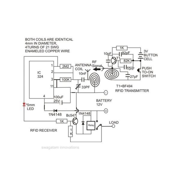
Constructing an RFID access control circuit at home and witnessing its functionality can be a remarkable experience. While the circuit may not be considered high-tech, its low cost combined with the satisfactory results achieved demonstrates a significant level of...
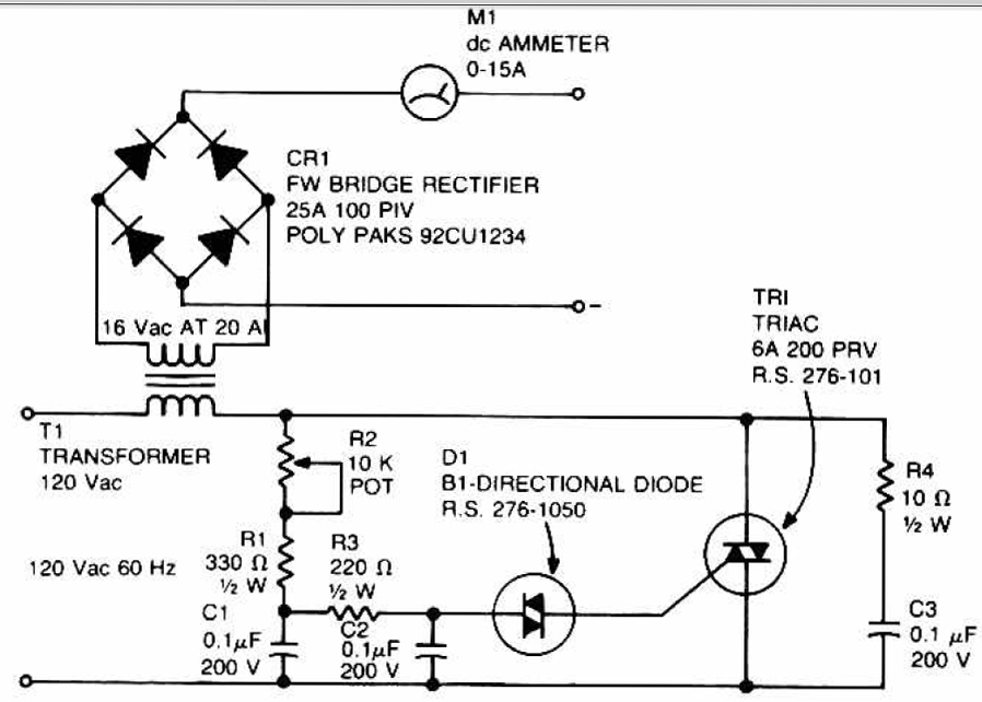
This circuit can be used to charge accumulator and cell batteries. It features a very stable output that extends the battery life and maximizes the added battery capacity. The charging process is also quite fast, optimizing the time required...
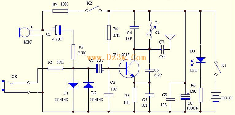
C4 and L form a resonator, where the resonant frequency corresponds to the FM transmitting power of the microphone. According to the component parameters in the diagram, the transmission frequency can range from 88 to 108 MHz. The frequency...

This is a simple yet effective charger for lead-acid batteries. It utilizes a 12-volt car bulb as both a current regulator and a charge status indicator. The described circuit is an innovative approach to charging lead-acid batteries. It employs...
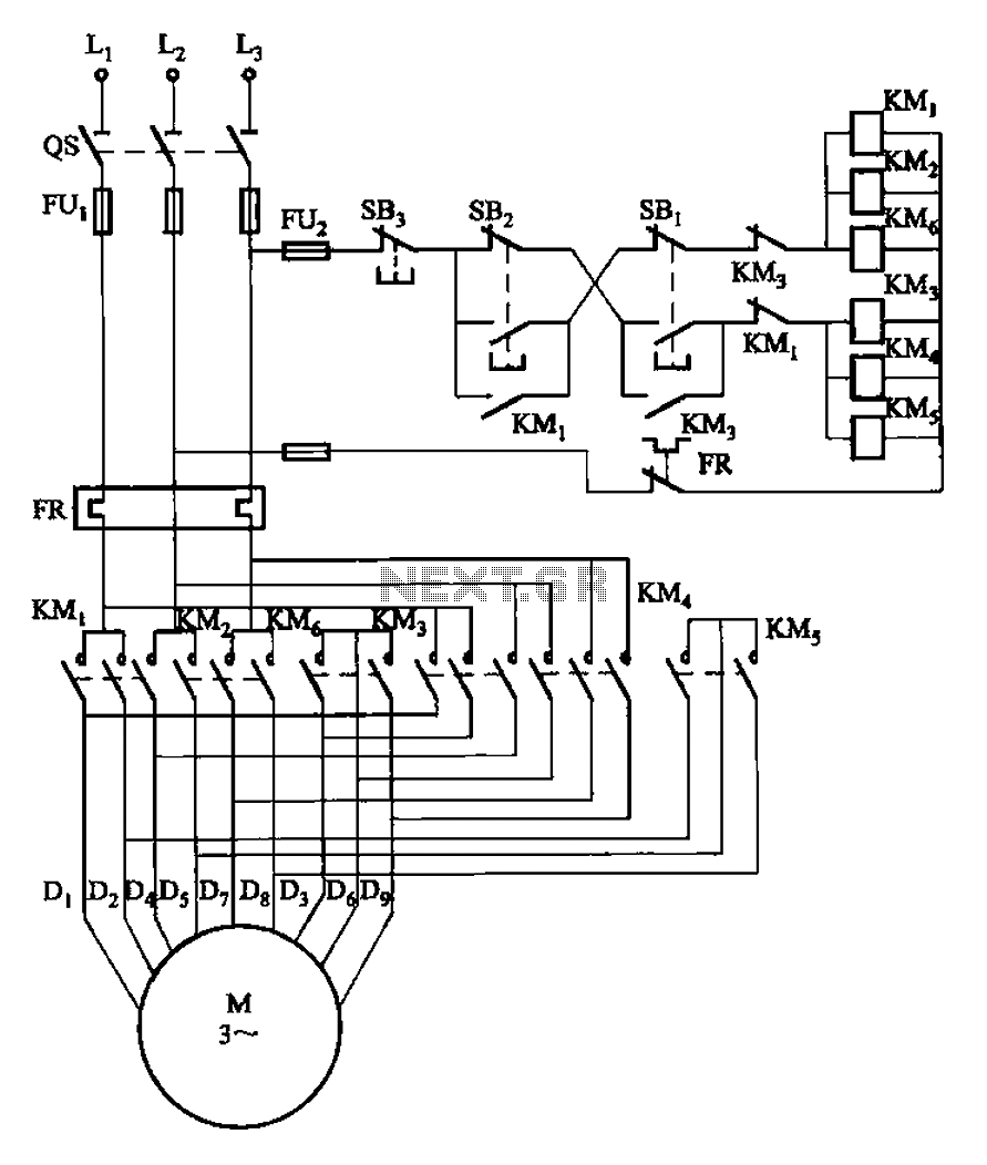
The circuit illustrated in Figure 3-107 features a low-speed operation button (SBi) and a high-speed operation button (SB2). The circuit design depicted in Figure 3-107 integrates two operational modes controlled by distinct buttons: SBi for low-speed operation and SB2 for...
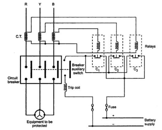
Consider a simplified circuit of a typical relay, which is usually part of a three-phase circuit with a complex contact system. The provided diagram illustrates a single-phase simplified circuit to clarify the basic operation of a relay. Part A...