
Crystal Oscillator Design

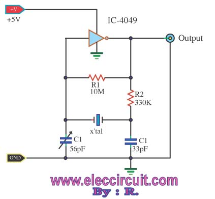
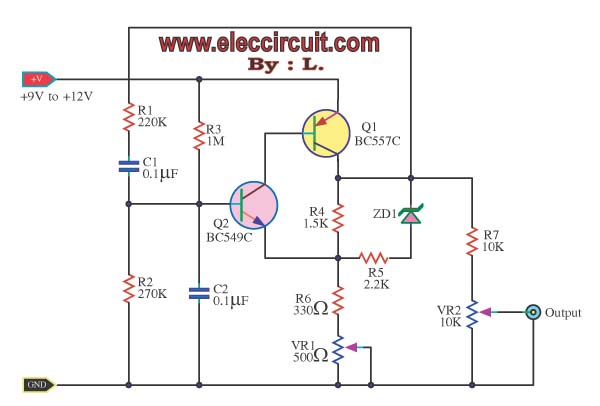
The crystal oscillator circuit utilizes a quartz crystal resonator to generate a stable frequency output. The primary components typically include the crystal, an amplifier (often a transistor or operational amplifier), and feedback components such as resistors and capacitors. In this specific circuit, the 3.5 MHz crystal serves as the frequency-determining element, ensuring that the oscillator maintains a consistent output frequency with minimal drift.
The circuit configuration can vary, but a common design involves the crystal connected in a feedback loop with an amplifier. The amplifier boosts the signal generated by the crystal, while the feedback network ensures that the output remains in phase with the input, thus sustaining oscillation. The stability of the output frequency is primarily influenced by the characteristics of the crystal, including its cut, temperature stability, and load capacitance.
In practical applications, crystal oscillators are widely used in clocks, timers, and frequency synthesis, where precise timing is crucial. The output waveform is typically a square wave, which may require further conditioning, such as filtering or shaping, depending on the intended application. Proper layout and component selection are essential to minimize noise and ensure reliable operation at the specified frequency.HI, i Just wanted to understand this circuit better and discuss with people So here it is a ,crystal oscillator It uses a 3.5Mhz Crystal and.. 🔗 External reference
Related Circuits
The circuit was designed to create a frequency converter using a crystal oscillator for the conversion of 10 MHz to 1 MHz. It incorporates a 7404 hex inverter. The circuit functions as a frequency divider, utilizing a crystal oscillator to...
Application note on designing linear and switch-mode (switching DC-DC converter current source) battery charger applications that require external microcontrollers and related system-level issues for notebook computers. The application note provides guidance on the design of both linear and switching DC-DC...
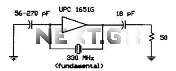
A /xPC 1651G IC operates in the fundamental mode with an experimental crystal at 330 MHz. The 56-to-270 pF capacitor is not critical; about +1 dBm RF output is available. The /xPC 1651G integrated circuit (IC) is designed to function...
A friend requires a pulse generator oscillator circuit that maintains a stable frequency of 32.768 kHz for a digital CMOS binary counter. The pulse generator oscillator circuit designed to operate at a frequency of 32.768 kHz is commonly used in...
In a sine wave oscillator circuit, a thermistor and an incandescent lamp are often utilized to stabilize the output of the circuit at a fixed value. The resistance of... The sine wave oscillator circuit is designed to generate a continuous...
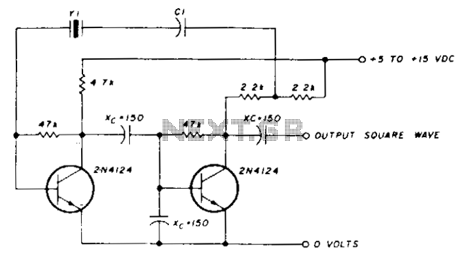
A capacitor in series with the crystal may be utilized to adjust the oscillator output frequency. The value may range between 20 pF and 0.01 µF, or it may be a trimmer capacitor, and it will approximately equal the...