
Crystal Oscillator Frequency Converter

The circuit functions as a frequency divider, utilizing a crystal oscillator to generate a stable 10 MHz signal. The 7404 hex inverter is employed to achieve the necessary signal manipulation for frequency conversion. Each inverter stage within the 7404 can be configured to create a series of toggling states that effectively halve the frequency of the input signal.
The crystal oscillator is the primary frequency source, ensuring precision and stability in the output frequency. The output from the oscillator is fed into the first inverter stage of the 7404, where the signal is inverted. This inversion process introduces a phase shift, which is critical for the subsequent stages of frequency division.
By cascading multiple inverter stages, the circuit can achieve the desired output frequency of 1 MHz. Specifically, two stages of inversion will divide the original 10 MHz signal down to 2.5 MHz, and further signal processing or additional inverter stages can be utilized to achieve the final 1 MHz output. The design may also include passive components such as resistors and capacitors to filter the output signal and stabilize the operation of the inverter stages.
This configuration is useful in various applications where a lower frequency signal is required from a higher frequency source, such as in signal processing, communication systems, and clock generation for digital circuits. Careful attention must be given to the power supply and grounding to minimize noise and ensure reliable operation of the frequency converter.The circuit was designed to create a frequency convert with the use of a crystal oscillator for the conversion of 10 MHz to 1 MHz. 7404 a hex inverter u.. 🔗 External reference
Related Circuits
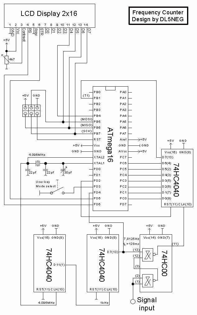
To ensure the circuit functions properly, it is crucial to correctly configure the fuse bits within the AVR microcontroller. These fuse bits can be set using the programmer employed to upload the software. For those interested in the technical...
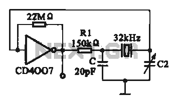
A 32 kHz clock oscillator is essential for digital circuits, as depicted in the schematic. The 32 kHz crystal clock oscillator serves to provide a time reference signal for the digital circuit. It utilizes a CMOS integrated circuit, specifically...
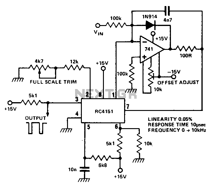
The RC 4151 precision voltage-to-frequency converter generates a pulse train output that is linearly proportional to the input voltage. The RC 4151 is a highly accurate voltage-to-frequency converter designed for applications requiring precise frequency output based on varying voltage levels....
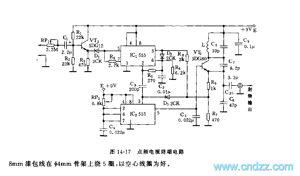
As shown in figure 14-17, this circuit consists of the input circuit, the line frequency synchronization generator, the sample-and-hold circuit, the voltage control delay generator, and the RF modulator. The input circuit includes the input attenuator RP1 and the...
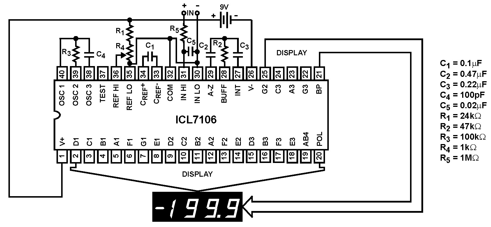
The Intersil ICL7106 and ICL7107 are high-performance, low-power, 3½ digit analog-to-digital (A/D) converters. They include seven-segment decoders, display drivers, a reference, and a clock. The ICL7106 is designed to interface with a liquid crystal display (LCD) and features a...
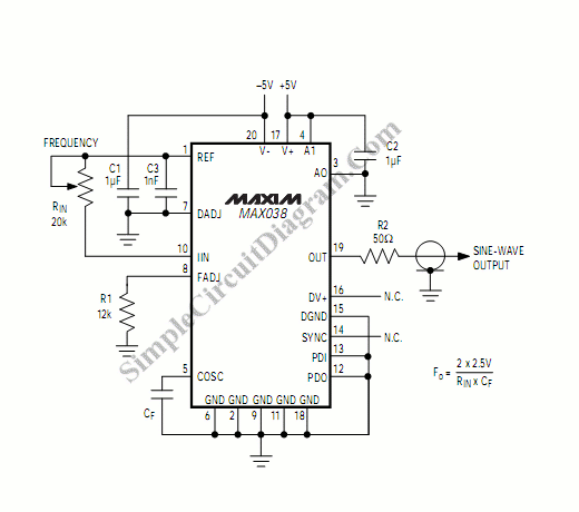
A function generator that operates within a frequency range of 0.1 Hz to 20 MHz can be easily constructed using the MAX038 integrated circuit chip. This describes a straightforward implementation of the device. The MAX038 is a precision waveform generator...