
Low-frequency oscillator 10-150khz

In oscillator circuits, the inclusion of a capacitor in series with the crystal plays a crucial role in fine-tuning the output frequency. The capacitor's value, which can vary from 20 picofarads (pF) to 0.01 microfarads (µF), or potentially be a variable trimmer capacitor, is selected to match the load capacitance specified for the crystal being used. This matching is essential to ensure that the oscillator operates at the desired frequency, as deviations can lead to frequency instability or inaccuracies.
The approximate nature of the capacitor and resistance values highlights the need for careful consideration during circuit design, as these values can differ based on the specific application and the frequencies involved. This variability necessitates a thorough understanding of the circuit's operational environment to ensure optimal performance.
Power supply decoupling is another critical aspect of oscillator design. It is recommended to use local decoupling capacitors placed close to the oscillator to filter out high-frequency noise and provide a stable power supply. This practice minimizes the risk of oscillation frequency drift caused by power supply fluctuations.
Additionally, in high-frequency circuits, it is imperative to maintain short lead lengths. Longer leads can introduce unwanted inductance and capacitance, which can adversely affect the circuit's performance, leading to signal integrity issues and potential oscillation problems. Therefore, careful layout and routing of traces are essential to preserve the high-frequency characteristics of the oscillator circuit.CI in series with the crystal may be used to adjust the oscillator output frequency· Value may range between 20 pF and 0.01 µ¥, or may be a trimmer capacitor and will approximately equal the crystal load capacitance. X values are approximate and can vary for most circuits and frequencies; this is also true for resistance values.
Adequate power supply decoupling is required; local decoupling capacitors near the oscillator are recommended. All leads should be extremely short in high frequency circuits.
Related Circuits
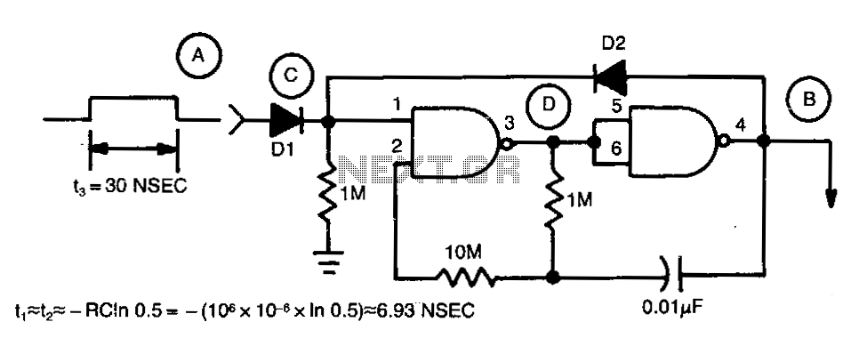
Regenerative feedback at capacitor C allows the oscillator to complete its timing cycle instead of shutting off immediately. The integrated circuit (IC) used was a CD4011AE, although an equivalent IC will also function. The described circuit utilizes regenerative feedback to...
The RF design and construction of radio frequency oscillators. Radio frequency (RF) oscillators are essential components in various electronic systems, generating signals at specific frequencies used for communication, signal processing, and other applications. The design of RF oscillators involves several...
This is an astable multivibrator (oscillator) circuit using a CMOS inverter. The circuit employs the CD4007 or MC14007 integrated circuit. The operating frequency range of this circuit is not specified. The astable multivibrator circuit utilizes CMOS technology to create a...
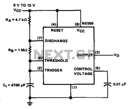
The NE555 timer is configured in astable mode and utilizes three timing components (RA, RB, and Ct). A 0.01 µF bypass capacitor is connected to pin 5 to enhance noise immunity. The operational limitations of the astable mode are...
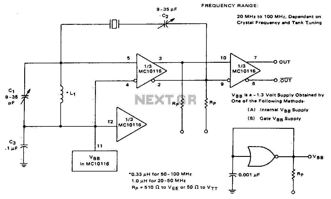
This circuit utilizes an adjustable resonant tank circuit that ensures operation at the desired crystal overtone. Capacitor C1 and inductor L1 form the resonant tank circuit, which can be adjusted to achieve a resonant frequency ranging from approximately 50...
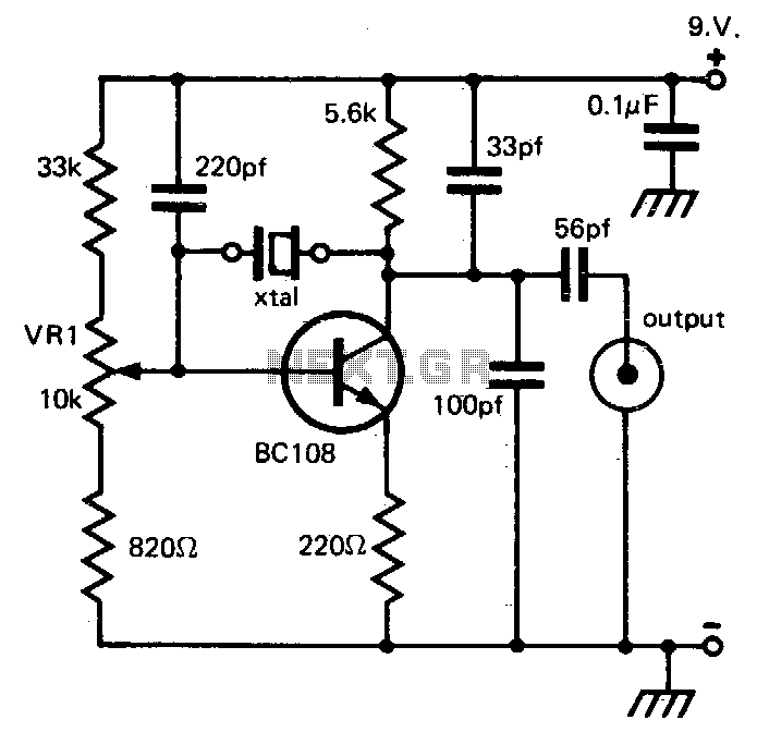
This circuit provides reliable oscillation and an output close to one volt peak-to-peak. Power consumption is around 1 mA from a nine-volt supply. The described circuit is likely a simple oscillator designed to generate a periodic waveform with a peak-to-peak...