
microprocessor based frequency counter

The AVR microcontroller's fuse bits play a critical role in determining the operational characteristics of the device. The configuration of these bits is essential for selecting the appropriate clock source, which directly impacts the performance and functionality of the entire circuit. The CKSEL bits, which are specifically designed to select the clock source, must be set according to the desired application. When configured to use the internal clock, the microcontroller operates at a default speed, which may be adequate for basic applications. However, for applications requiring higher precision timing or synchronization, the use of an external crystal oscillator is recommended.
The CKOPT bit further enhances the performance of the oscillator circuit. By enabling full amplitude output, it ensures that the signal integrity is maintained, allowing downstream components, such as the 74HC4040 frequency divider, to function effectively. The 74HC4040 relies on a stable and robust clock signal to produce accurate frequency division, making the proper configuration of the CKOPT bit essential for reliable operation.
Overall, understanding and correctly setting the fuse bits of the AVR microcontroller is vital for achieving optimal circuit performance. Careful attention to the configuration of CKSEL and CKOPT bits can significantly influence the behavior of the microcontroller and its interaction with other components in the circuit. Therefore, thorough knowledge of the ATmega16 datasheet and the implications of fuse bit settings is necessary for engineers and technicians involved in designing and implementing AVR-based systems.In order to make the circuit work, it is important to set the fuse bits inside the AVR micro controller correctly. Theses fuse bits can be set with the programmer that is used to flash the software. For those that are interested to understand the background, have a look at the ATmega16 datasheet pages 254-256.
The logic of the bits is active low, i. e. programmed=0, unprogrammed=1. The bits that determine the clock source of the AVR, CKSEL 0. 3, come programmed when the chip is shipped, i. e. set to 0. That is the reason why the controller runs on internal clocking, and does not even start the crystal. By setting all CKSEL 0. 3 to unprogrammed (1), the external crystal is selected. The CKOPT programmed (0) switches the crystal from weak amplitude to full amplitude, so that the 74HC4040 gets enough input signal.
🔗 External reference
Related Circuits
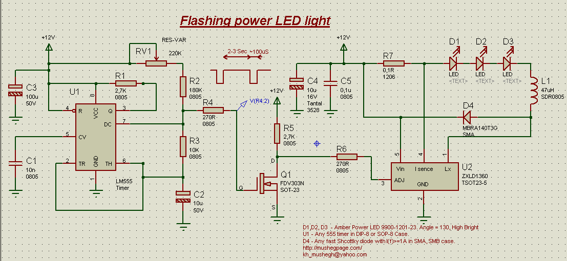
This project demonstrates the construction of a simple flashing light circuit using the IC 555 timer. The 555 timer functions as a clock generator with a duty cycle of less than 100% and greater than 50%. Additional components include...
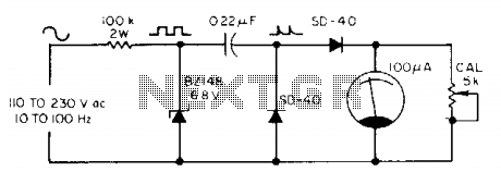
The meter utilizes a zener diode to convert input sine waves into square waves. After calibration with a 5 k ohm potentiometer, the 100 µ meter provides a direct reading in hertz. The circuit employs a zener diode as a...
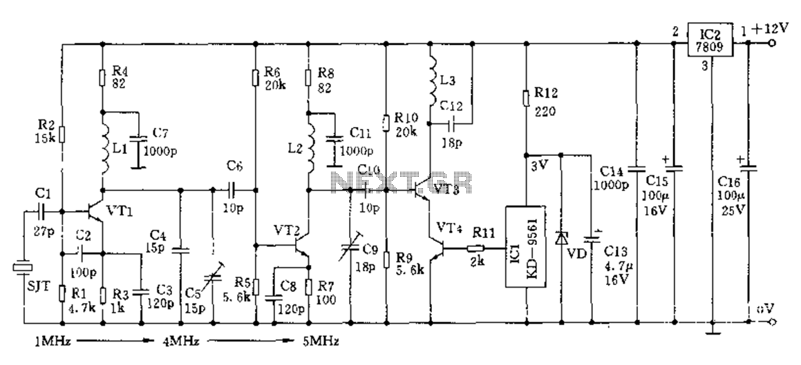
The crystal frequency stabilization of a frequency modulation circuit is illustrated below. The frequency modulation (FM) circuit utilizes crystal frequency stabilization to ensure precise frequency control and stability. This process involves the use of a quartz crystal oscillator, which...
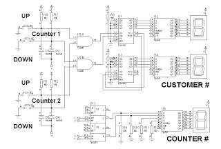
This is a simplified design utilizing an up/down counter integrated circuit (IC), specifically the 74192. This versatile logic IC features separate pins for counting both up and down. Additionally, an RS latch is incorporated to indicate the current counter...
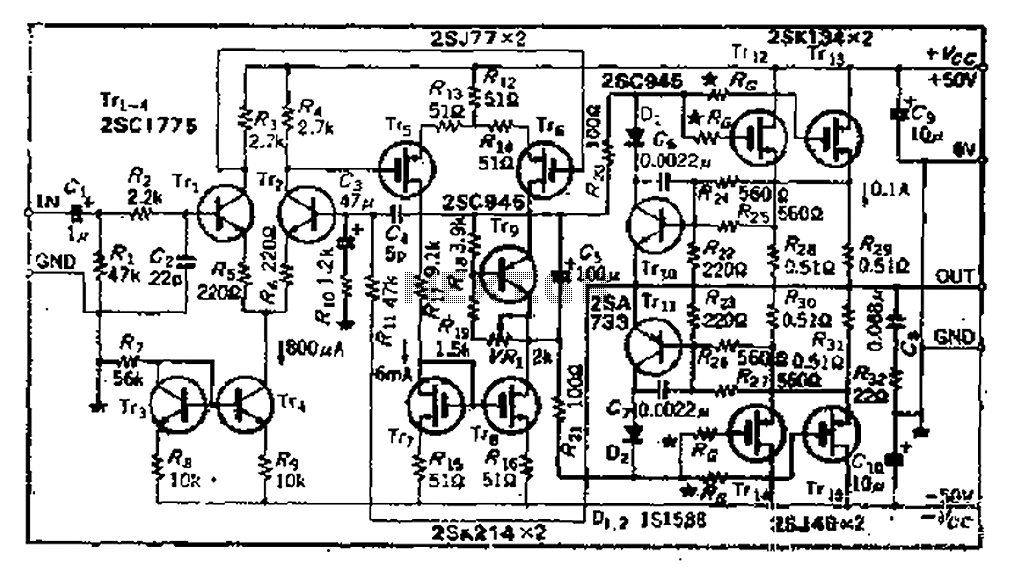
The circuit consists of three identical basic stages, with the second stage featuring a differential output from the power MOSFET, 2SJ77. A current mirror circuit utilizing 2SK214 is implemented. The operating current is 6mA; however, due to the power...

This circuit measures capacitance by the time it takes for an unknown capacitor to reach 6.32 V (which is 63% of 10 V or one time constant, 1RC) when charged through resistor R. The LED, used as a timebase,...