
Operation of an Pierce Oscillator

The Pierce Oscillator is an essential component in various electronic applications, particularly in frequency generation and signal processing. It operates by leveraging the piezoelectric properties of the crystal, which provides precise frequency stability. The oscillator circuit typically consists of a PNP transistor, a crystal, and a tank circuit formed by capacitors and resistors.
In a typical configuration, the PNP transistor is biased to operate in the active region, allowing it to amplify the oscillations. The crystal is connected in the feedback loop, which ensures that the oscillator operates at its fundamental frequency. The tank circuit, composed of two capacitors, creates a resonant circuit that enhances the stability and purity of the oscillation frequency.
The choice of the PNP transistor is critical, as it must be capable of providing sufficient gain at the desired operating frequency. The 2N3904 and 2N3906 are popular choices due to their high-frequency performance and availability. The resistors in the circuit must be selected carefully to ensure proper biasing of the transistor, which is crucial for maintaining stable oscillation.
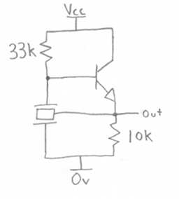
The voltage divider formed by resistors Rf and Rb is responsible for setting the base voltage of the transistor. This configuration allows for fine-tuning of the oscillator's frequency and amplitude. The overall design must ensure that the supply voltage (Vcc) is within the operational limits of the chosen transistor to prevent damage and ensure reliable operation.
In summary, the Pierce Oscillator is a versatile and widely used circuit in electronics, providing high-frequency oscillation with excellent stability. Its design involves careful selection of components and precise calculations to achieve the desired performance characteristics.A Pierce Oscillator is a type of oscillator that uses a crystal instead of a parallel-resonant circuit [LC circuit]. A pierce oscillator also uses the voltage developed from a tap between two capacitors in the tank circuit, as shown to the right.
range. Both of the Pierce Oscillators use a PNP transistor as the amplifier. Basically any PNP transis tor may be used as long as it exhibits gain at the desired frequency of operation. Two common general purpose PNP transistors include the 2N3904 PNP Transistor and 2N3906 PNP Transistor. Both of these transistors offer frequency operation over 100MHz. The important criteria is that the transistor provides amplification in the frequency range of oscillation.
Both of these circuits are very similar. The DC voltage is supplied by Vcc, set to be in range of the transistor selected. The 2N3904, for example, has a maximum Collector-Base voltage of 60 volts and Collector-Emitter voltage of 40 volts. The DC bias currents are set by a number of resistors. Resistor Re sets the emitter current. The collector current is set by resistor Rc. The Base voltage is set by the voltage divider formed by resistors Rf and Rb and is equal to Vcc x Rb/(Rb + Rf)].
🔗 External reference
Related Circuits

A voltage-controlled oscillator (VCO) operates similarly to a voltage-to-frequency converter (VFC). Its output frequency is determined by a control voltage input. In the circuit diagram, 'd' represents the amplifier input voltage, which is set to 0.6V, while 'h' denotes...
The output frequency can be altered based on the division ratio of the comparison frequency in the 10 kHz unit, with the division ratio set to 1024 in this circuit. Given that the amateur radio bandwidth in Japan is...
A ceramic resonator can be utilized to construct an oscillator. A single digital inverter can be employed to create a Pierce oscillator. To design a Pierce oscillator using a ceramic resonator and a digital inverter, the following components and configurations...
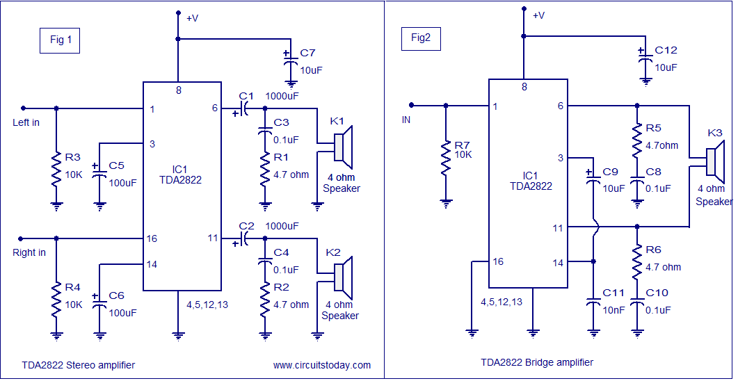
The TDA2822 audio amplifier circuit provides 1.35W output into a 4-ohm speaker when powered by a 6V supply. It supports both bridge and stereo modes and operates within a supply voltage range of 3V to 15V, making it suitable...
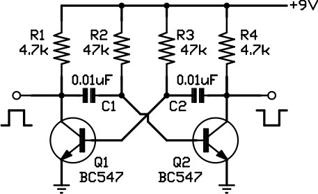
This circuit is one of the simplest to implement but can be challenging to comprehend. It consists of a two-transistor oscillator known as an astable multivibrator, which generates a square wave output that is out of phase. Initially, it...
The voltage Vc1 increases linearly when the pull-up resistor RA in the monostable circuit is replaced with a constant current source, resulting in a linear ramp. The circuit for generating the linear ramp and the corresponding waveforms are illustrated...