
Crystal pickup pre-amplifier circuit
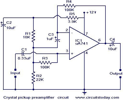
The described preamplifier circuit is designed to enhance the output signal from high-impedance crystal pickups, which are commonly used in applications such as musical instruments. The non-inverting configuration allows for a straightforward amplification of the input signal while maintaining phase integrity. The gain of the amplifier is adjustable through the feedback resistor R4; this design offers flexibility in tuning the signal amplification according to specific requirements.
Capacitor C3 plays a critical role in defining the low-frequency response of the amplifier. By selecting an appropriate value for C3, the designer can control the point at which the amplifier begins to attenuate lower frequency signals, thus tailoring the circuit's response to suit the characteristics of the pickup being used.
The voltage divider network, consisting of resistors R1, R2, and R5, is essential for establishing a stable DC bias at approximately half the supply voltage. This biasing ensures that the amplifier operates within its optimal range, preventing distortion and allowing for a clean amplification of the audio signal.
Furthermore, the combination of resistor R5 and capacitor C2 serves as a low-pass filter, which is crucial in minimizing unwanted hum and noise that may arise from power supply fluctuations or interference. This filtering capability is particularly important in environments where multiple devices share a common power supply, helping to ensure that the preamplifier delivers a high-quality audio signal free from unwanted artifacts.
Overall, this preamplifier circuit is a well-designed solution for enhancing the performance of high-impedance crystal pickups, providing adjustable gain, stable biasing, and effective noise reduction.A preamplifier operating on a single supply and suitable for use with high impedance type crystal pickups is shown here. The circuit is basically a non-inverting AC amplifier in which the gain is dependent on the feedback resistor R4.
The smaller is the R4, the lower will be the gain. The low frequency roll off characteristics are decided by C3. Volta ge divider network comprising of R1, R2 and R5 provide a DC bias of about half the supply voltage R5 and C2 from a supply line filter to reduce the hum level as well as to reduce the chances growling when the preamplifier is operated from common power supply. 🔗 External reference
Related Circuits
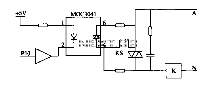
Device for an intermediate relay. The circuit utilizes a Triac AC contactor interface, employing the MOC3041 Triac output optical coupler to trigger the Triac. When Pl0 is low, the Triac will be activated, energizing the AC contactor coil. The described...
This FM spy transmitter can function as a bug transmitter or a DIY FM bug. It utilizes a single IC 74F13, one coil, a capacitor, and one additional component. The FM spy transmitter is a compact device designed for covert...
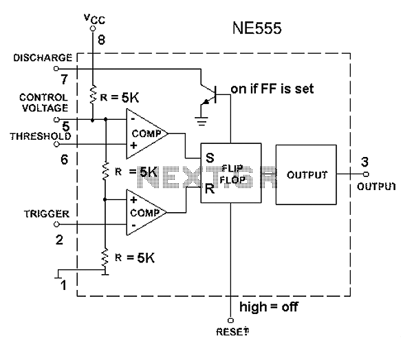
The 555 timer circuit, regardless of the manufacturer, has a consistent internal structure and performance. Various manufacturers produce different models of the 555 timer, including MC555, CA555, XR555, LM555, as well as domestic models like SL555, FX555, and 5G1555....
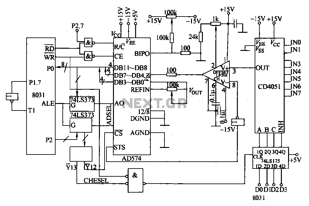
Converters and data sampling: A 12-bit A/D converter, AD574, is interfaced with an 8031 microcontroller circuit. Parameters are measured by a multi-way switch after a CD4051 strobe signal is sent to the sample/hold input device. The selection of the...
For several years, a rear fog lamp has been mandatory for trailers and caravans to enhance visibility in foggy conditions. When this fog lamp is activated, the fog lamp of the towing vehicle must be turned off to prevent...
This is an inexpensive DC voltage doubler circuit diagram that requires a minimal number of components and is capable of delivering 10V from a 5V power supply. If the oscillator needs to be... The circuit operates on the principle of...
Warning: include(partials/cookie-banner.php): Failed to open stream: Permission denied in /var/www/html/nextgr/view-circuit.php on line 713
Warning: include(): Failed opening 'partials/cookie-banner.php' for inclusion (include_path='.:/usr/share/php') in /var/www/html/nextgr/view-circuit.php on line 713