
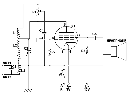
Crystal Radio

The described circuit represents a simple AM receiver employing a 2N5484 JFET as the active component. The circuit's design is centered around a tuning coil, where the source connection is strategically tapped low down to facilitate impedance matching with headphones, functioning as the anode. The drain connects to the headphones, acting as the cathode, thereby completing the detector circuit. This configuration allows for efficient signal reception and processing.
The antenna system consists of a short antenna paired with a water pipe ground, which has shown to yield effective results despite conventional wisdom suggesting longer antennas would be preferable. The tuning coil's bottom tap position has been found to work optimally in this setup, although it may lead to frequency band shifts. The circuit utilizes an air-cored inductor, wound with PVC insulated wire for optimal performance, avoiding enamelled copper wire due to its potential impact on sensitivity and selectivity.
In terms of component selection, the use of high-quality, untinned multi-stranded hookup wire is recommended for winding the tuning coil. The option to use a ferrite rod antenna coil is also available, with adjustments required to the number of turns for compatibility with the specified tuning capacitor values. Taps on the coil are established to facilitate connections for the antenna and source, allowing for further experimentation to optimize reception.
The circuit diagram illustrates the essential connections and layout based on the QST design, with particular attention to the fixed plates of the variable capacitor (VC1) and the headphone connections. This design not only enhances the understanding of the circuit's operation but also serves as a foundation for further experimentation and improvement in AM reception capabilities.The source connection is tapped into the tuning coil low down, as a means of impedance matching with the headphones and acts as the anode, while the drain connects with your headphones as the cathode, to complete the detector part of the circuit. According to the experts on the net, much success has been enjoyed by one and all, and there's a lot of chatter about this most recent innovation in the realm of simple AM receivers (292 posts so far, to the 'Rap'n'tap' chatroom of the American Crystal Set Society alone!- www.midnightscience.com).
One of the most curious aspects of this little beauty is that the antenna/ground system I employ basically entails a 'short' antenna, and a water pipe ground. Ideally, short antenna wires work best near the top of the tuning coil, but in this case, the best position seems to be right at the bottom tap!
Normally, this would send all my weak locals into a spin, and shift the whole band up towards the top end of the tuning cap's range. What is presented in this article, is my version of the QST arrangement, and I'm using the humble 2N5484 JFET, purchased from JAYCAR Electronics for around $2.00. Yes, a JFET, not a MOSFET! Why? Well, my basic knowledge of FET devices at the time of acquiring the QST design was a little rusty, to say the least, not having experimented with them for some time, so after a bit of scratching around on the net, and down at the local library, I reclued myself as to their peculiarities.
Devices that are static sensitive have protection diodes on the inputs, and the ALD device certainly has those. Basic JFETs also have a protective diode between the gate and source connections, presumably for the same reason, but neither the QST design, nor my adaptation of it, use any internal diodes as a rectifier.
You can experiment with that as a start - simply replace your germanium or Schottky diode with the gate and source of a JFET device, and you'll get reception all right - but it does seem a bit mushy or scratchy, somewhat like a poor Schottky diode that distorts on low signal levels (BAT46's come to mind?) You can still obtain reasonable results by tapping the gate further up the tuning coil, if you want to. This version of the receiver will work quite OK with air cored inductors, providing you use PVC insulated wire.
I don't recommend enamelled copper wire, as it can be down a bit on sensitivity and selectivity. Get some good quality, thinnish and untinned (copper colour, not silvered colour) multi stranded hookup wire for winding the tuning coil and a tube made of plastic, rather than cardboard. If you want to use a ferrite rod antenna coil instead, then go right ahead, Ones that come from el-cheapo pocket radios will work but you will need to remove some of the turns from the primary coil for them to work with a combined 160+60pF PVC tuning cap, and then create one low Z tap, by soldering the end of the primary coil to the start of the smaller secondary coil.
If you can get your hands on some high Q 'litz' wire, then use that on a bare ferrite rod. Simply fasten the wire onto one end of the rod using some tape, then wind on around 50 to 60 turns, with two taps - one at five turns from the grounded end (for the antenna lead in) and the other one at ten turns for the Source (anode) connection. You may need to experiment with the number of turns, and the tapping points on the coil, depending on the value of VC1.
To the left you can see a basic circuit diagram of my radio, based on the QST design, and to the right, a physical wiring diagram of how it all goes together. Note that both sections of VC1's fixed plates (A and O) are wired together, and that your headphone connections go between 'd' of the FET and the common ground 'G' point.
🔗 External reference
Related Circuits
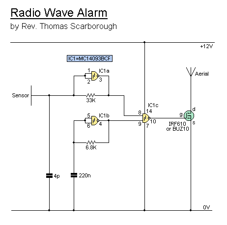
This simple alarm circuit can effectively alert users to the presence of an intruder, providing notification before they even reach the doorstep. The circuit is designed to be straightforward and efficient, utilizing basic electronic components to create an effective security...

The SI2171 is a sub-package of the SI2170. For further details, please refer to the SI2170 description. The datasheet for the SI2171 can be downloaded from the link provided below. By Silicon Laboratories. The SI2171 is a versatile integrated circuit...
Crystal 80mW FM transmitter circuit diagram of the production The Crystal 80mW FM transmitter circuit is designed to generate frequency modulated (FM) signals suitable for short-range audio transmission. This circuit primarily consists of a crystal oscillator, which serves as...
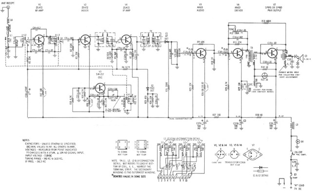
The Motorola VWA63 Auto Radio is an automotive all-transistor superheterodyne AM radio designed for standard broadcast reception. The accompanying schematic illustrates its configuration. The Motorola VWA63 Auto Radio utilizes a superheterodyne architecture, which is a common design for AM radios...
A regenerative radio operates by feeding back a small portion of the amplified output from the detector into the input. This feedback mechanism enhances sensitivity significantly beyond what a detector can achieve on its own. The simple regenerative radio...
This page is provided to the domain owner free by Sedo's Domain Parking. Disclaimer: The domain owner and Sedo maintain no relationship with third-party advertisers. References to any specific service or trademark are not controlled by Sedo or the...