
PWM Motor Speed Control Circuit with Diagram for DC Motor

The PWM (Pulse Width Modulation) motor speed control circuit utilizes the CD40106B integrated circuit, which is a Schmitt trigger inverter. This design is particularly suitable for controlling the speed of low-power DC motors by varying the duty cycle of the PWM signal delivered to the motor.
The circuit typically consists of the CD40106B, resistors, capacitors, and the DC motor. The Schmitt trigger inverter provides a stable output that can drive the MOSFET or transistor used to control the motor. The frequency of the PWM signal is determined by the values of the resistors and capacitors connected to the input of the inverter.
When the circuit is powered, the capacitor charges and discharges through the resistors, generating a square wave output. By adjusting the resistance or capacitance, the duty cycle of the PWM signal can be altered, which effectively changes the average voltage supplied to the motor. This results in variable speed control, allowing for precise adjustments to the motor's operation.
The schematic diagram typically shows the connections between the CD40106B, the power supply, the motor, and the control components. It is essential to ensure that the components are rated appropriately for the voltage and current requirements of the motor to prevent damage. Additionally, the circuit can be enhanced with features such as an on/off switch or feedback mechanisms for more advanced control.
This PWM motor controller is an efficient and straightforward solution for applications requiring speed regulation of low-power DC motors, making it suitable for hobby projects and small-scale automation systems.A simple PWM motor speed control circuit with diagram and schematic for low power dc motors. This easy to make pwm dc motor controller is made using IC CD40106B.. 🔗 External reference
Related Circuits

This circuit was designed by Lazar Pancic from Yugoslavia. A typical PC sound card includes a microphone input, speaker output, and occasionally line inputs and outputs. The microphone input is specifically tailored for dynamic microphones with an impedance range...
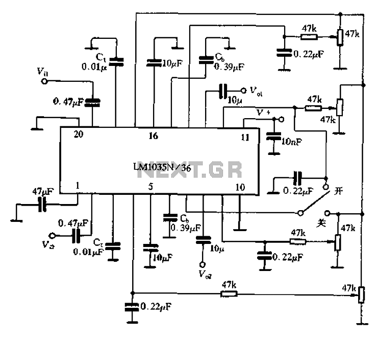
The circuit includes a loudness compensation control terminal at pin 7, which, when combined with the DC control voltage, forms a simple loudness compensation mechanism that enhances bass response. When the loudness control switch is in the OFF position,...

This circuit is similar to the one found in the Single Buss 1V/Octave Keyboard Controller. Refer to the circuit description there for more details. This board includes additional resistors used in the keyboard voltage divider. In a typical keyboard,...
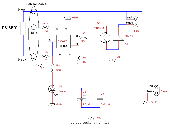
This is a fan controller designed for an audio/video cabinet. It utilizes a PICAXE 08M microcontroller and a DS18B20 temperature sensor. The fan activates at 30 degrees Celsius (approximately 86 degrees Fahrenheit) and deactivates at 28 degrees Celsius (around...
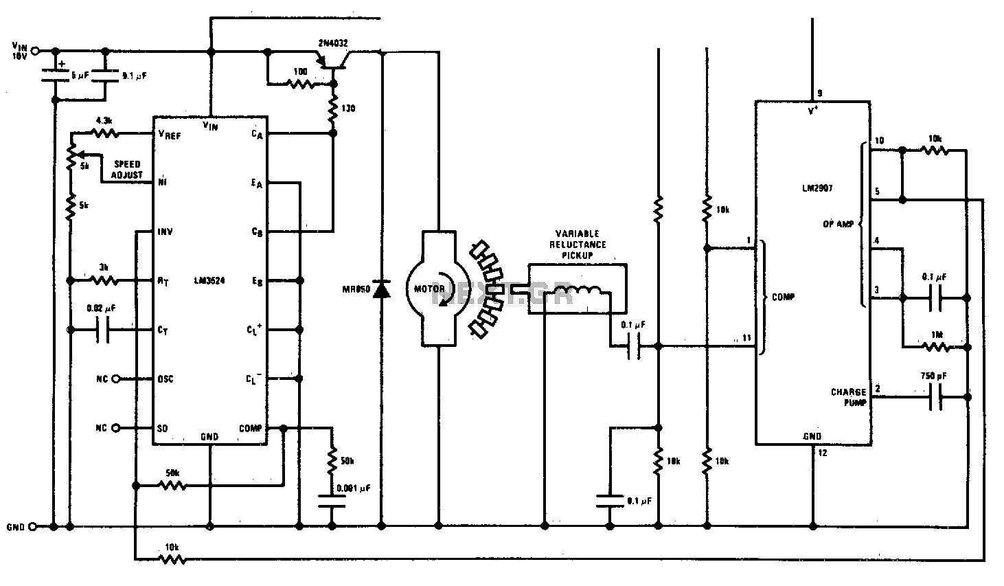
This circuit is a regulating series DC motor speed control using the LM3524 for the control and drive of the motor and the LM2907 as a speed sensor for the feedback network. The circuit employs the LM3524 integrated circuit, which...
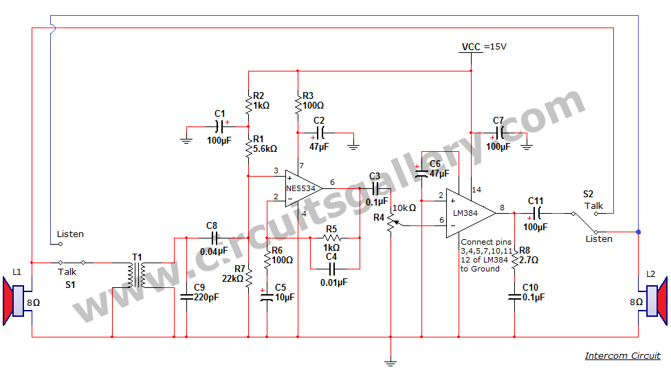
An intercom or intercommunication circuit is a two-way communication system that provides a reliable communication line and is easy to implement. The circuit consists of an amplifier, two switches, and two loudspeakers, allowing for the extension of the system...