
Cumulative timer circuit diagram

The cumulative timer circuit operates by utilizing a combination of resistors, capacitors, and diodes to create a timing function. Resistor R1 serves as the primary timing resistor, influencing the charge and discharge cycles of the capacitor C, which determines the timing intervals. The choice of metal film resistors for R1, R2, R3, R4, and R5 is significant due to their stability and precision, which are essential for accurate timing applications.
The internal crystal oscillator, characterized by its stable frequency output, provides a reliable clock signal to the circuit, ensuring that timing is consistent over extended periods. The capacitor C, being an aluminum electrolytic type, is selected for its ability to handle voltages exceeding 10V, which is crucial for applications where higher voltage levels may be encountered.
The diodes VD1 to VD4, specifically the 1N4007 rectifiers, are employed for their robustness in handling reverse voltage and ensuring proper rectification in the circuit. These diodes facilitate the conversion of alternating current (AC) to direct current (DC), which is necessary for the functioning of the timer circuit. The additional diode VD5 may be used for protection or as part of a more complex timing mechanism, depending on the specific design requirements.
In summary, this cumulative timer circuit is designed for precision timing applications, utilizing high-quality components to ensure reliability and accuracy. The combination of resistors, capacitors, and diodes forms a well-structured timing mechanism suitable for various electronic applications.The cumulative timer circuit consists of resistor R1 and spreadsheet internal crystal oscillator BC, and it is shown as the chart. R1 and R2 choose the metal film resistors: R3 ~ R5 select the 1/8W metal film resistors. C select the aluminum electrolytic capacitor with voltage being above 10V. VD1 ~ VD4 use the 1N4007 silicon rectifier diodes; VD5 uses the 1.. 🔗 External reference
Related Circuits
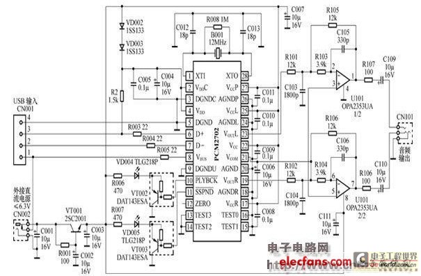
The peripheral circuit is straightforward, consisting of a DAC schematic circuit diagram for a USB interface that utilizes the PCM2702. The output of the circuit can be directly connected to a power amplifier and is capable of driving headphones...
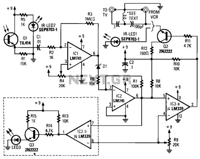
A signal from an infrared (IR) remote control is converted from IR radiation to a frequency pulse that can be transmitted through coaxial TV cable or any other two-conductor wire to another room, where it is converted back into...
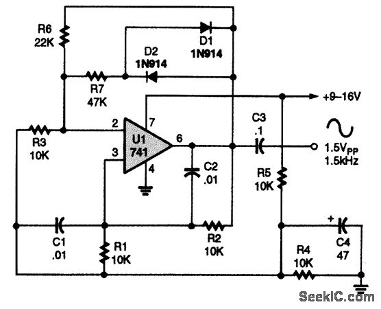
A 741 operational amplifier is configured within a Wien-bridge audio sine-wave oscillator circuit. The components C1, C2, R1, and R2 are responsible for determining the operating frequency of the circuit. By utilizing NPO capacitors and metal-film resistors, the oscillator...
The figure illustrates a preset outage timer circuit designed for an electric cooker. The timing range of the circuit extends from 1 hour to 12 hours, adjustable via a potentiometer (PR). The timing mode operates on a counting basis,...
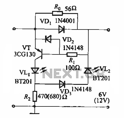
During the charging process, the green light-emitting diode (LED) VLi indicates that the battery is sufficiently charged, while the red light-emitting diode (LED) VLz illuminates when the battery is low. The circuit involves two light-emitting diodes (LEDs) serving as indicators...
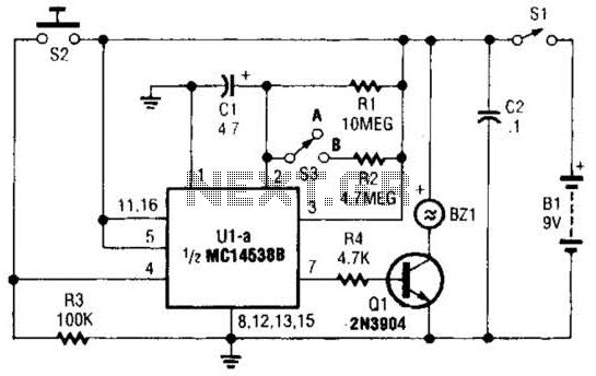
This circuit emits a loud tone if the input switch (S2) is not retriggered at designated intervals. If the user falls asleep and fails to re-trigger the circuit, it will continue to sound until S2 is pressed. The circuit operates...