
No Doze Alarm Circuit

The circuit operates on a fundamental principle of timing and alerting through sound. It typically includes a timer component, such as a 555 timer IC, configured in monostable mode, which generates a tone when the switch S2 is not activated within a specific time frame. The timer's output can be connected to a piezo buzzer or a speaker, producing a loud tone to alert the user.
When the circuit is powered on, the timer begins counting down from a preset interval. If the switch S2 is pressed within this interval, the timer is retriggered, resetting the countdown. However, if the switch is not activated before the timer reaches zero, the output goes high, activating the sound-producing element.
To ensure reliability, the circuit may also include a resistor-capacitor (RC) network that defines the timing interval, along with a diode to prevent back EMF from damaging the timer during operation. Additionally, a power supply circuit may be integrated to provide the necessary voltage levels for the timer and sound output device.
Overall, this circuit serves as an effective alert mechanism, ensuring that users remain aware of their need to interact with the switch at regular intervals, thereby preventing oversleeping or missing scheduled tasks. This circuit sends out a loud tone if the input switch (S2) is not retriggered at preset intervals. If you fall asleep and miss re-triggering the circuit, it will sound until you press S2.
Related Circuits
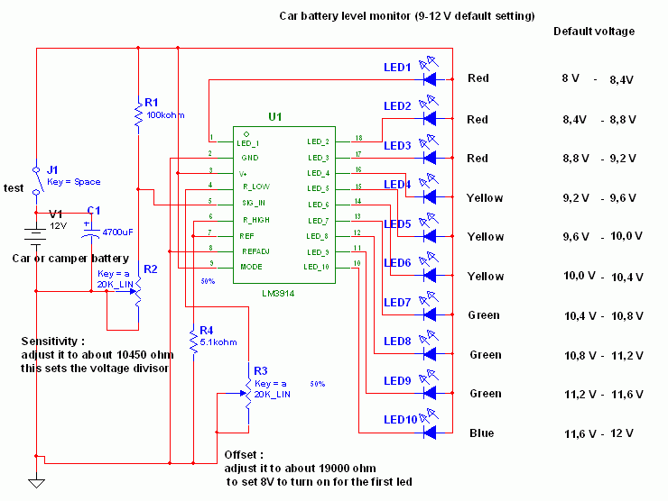
This circuit utilizes the widely available LM3914 integrated circuit (IC). The IC is straightforward to operate, does not require external voltage regulators due to its built-in voltage regulation feature, and can be powered from nearly any voltage source. The LM3914...
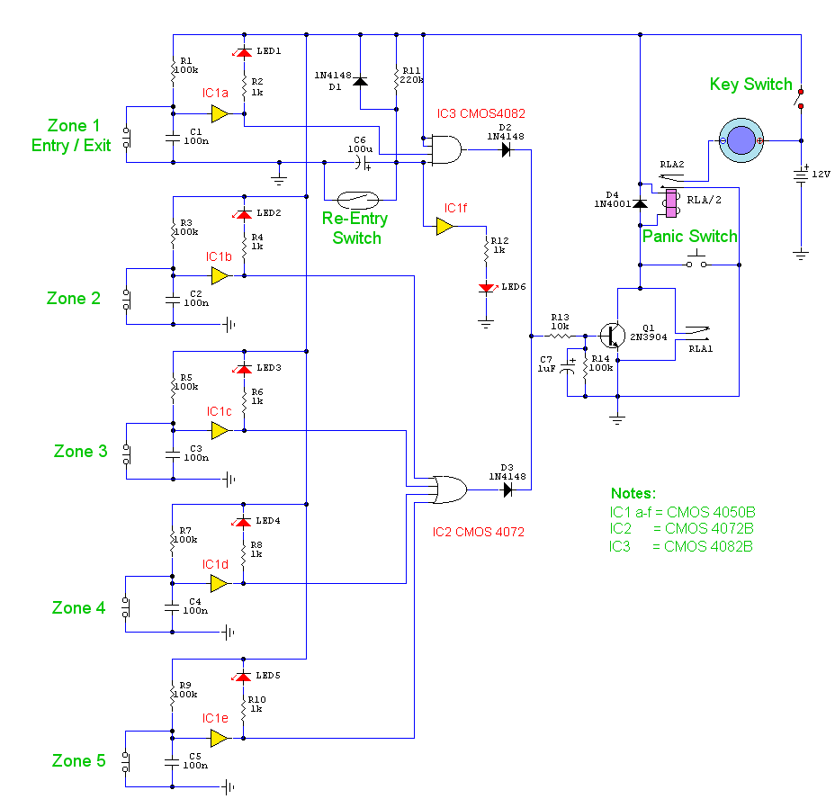
This is a complete alarm system with five independent zones suitable for a small office or home environment. It utilizes three CMOS integrated circuits and features a timed entry/exit zone, four immediate zones, and a panic button. There are...
Two circuits for laser transmitters are described. The first circuit utilizes a simple laser pointer module, with 3 or 5mW devices functioning effectively. Higher power units are often imported from the USA or Hong Kong compared to UK approved...
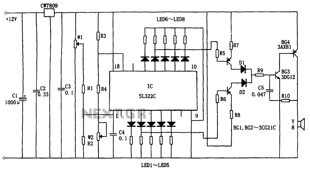
The circuit illustrated in the figure is a hydraulic oil level alarm system for automotive applications. It consists of a light-emitting diode (LED) driver, the SL322C integrated circuit (IC), a voltage regulator circuit (CW7809), and hydraulic oil level sensors...
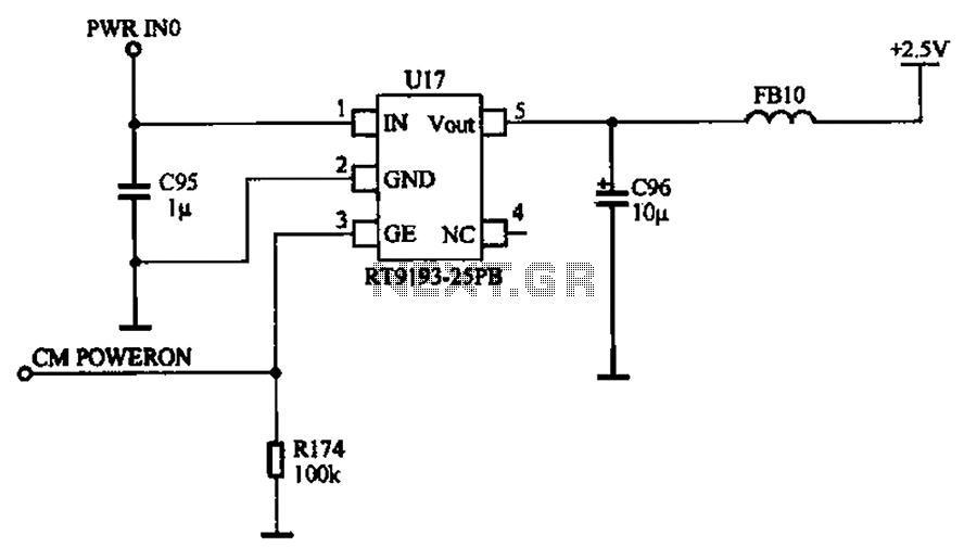
The camera power supply circuit illustrates the essential power supply required for the proper functioning of the camera. This power supply circuit is composed of a stable voltage control integrated circuit. The camera power supply circuit is critical for ensuring...
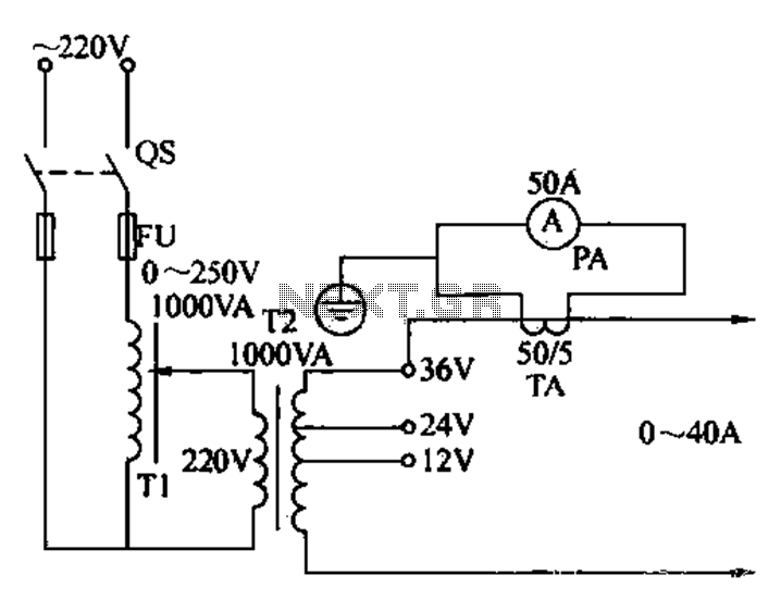
Electricians sometimes use overcurrent relays, thermal relays, and other devices to perform periodic overcurrent checks with a current generator. A secure running lights transformer, voltage regulator, and meter can be constructed using a small electric current generator. The homemade...