
Current Limiting for Redundant Power Systems

The TPS2359 hot-plug controller is designed with advanced features that cater specifically to the needs of AdvancedMC modules within telecom applications. It supports a dual-channel architecture, which allows for comprehensive management of power distribution across multiple modules. The integration of current limiting and fault protection mechanisms enhances reliability, ensuring that each module operates within safe parameters.
The controller's ability to maintain a fixed current limit through its multiswap feature is particularly advantageous in scenarios where multiple power supplies are connected. This ensures that the load remains stable, even as the configuration of power sources changes, which is essential for maintaining uninterrupted service in telecom applications.
In terms of circuit design, the TPS2359's current limiting functionality is implemented through a feedback mechanism involving precision resistors and operational amplifiers. This design choice not only meets the ATCA specifications but also allows for flexibility in component selection, enabling engineers to optimize the circuit for their specific applications. The use of external resistors for setting current limits allows for easier adjustments and fine-tuning to accommodate different load requirements and operational conditions.
Furthermore, the programmable fault timers provide an additional layer of protection, allowing the system to respond appropriately to prolonged current limit conditions. This feature is critical in preventing damage to the system components, particularly in high-stress environments where overheating and overcurrent situations may frequently occur.
Overall, the TPS2359 hot-plug controller is an essential component for designing robust and efficient power management solutions in AdvancedMC applications, ensuring compliance with industry standards while providing the necessary protections to enhance system reliability and performance.The new TPS2359 hot-plug controller integrates all of the power management functions for two AdvancedMC (AMC) modules. Its current limiting circuitry enables designers to meet tight AMC requirements. This is relevant because many applications use redundant supplies. A unique feature called multiswap maintains a fixed current limit, regardless o f the number of supplies connected to the load. The Advanced Telecom Computing Architecture (ATCA) standard provides a modular approach to designing telecom equipment. Adoption of this industry standard speeds product design and simplifies field upgrades. In the ATCA architecture, each carrier blade is required to contain up to eight AMC modules. These modules require hot-plug protection. The carrier board distributes two main power supplies to each AMC module: a 3. 3V management power supply, and a 12V payload power supply. In order to help designers meet these requirements, the TPS2359, a full featured dual-slot AdvancedMC controller was designed to provide all of the protection and monitoring circuitry required to support two AMC modules.
The controller fully integrates management power inrush control, over-current protection, and FET ORing. Adding two external power transistors provides each payload power channel all of these same features.
Figure 1 shows a simplified block diagram of a two-channel AMC application where both channels draw from common supplies. They can also draw from independent supplies. This unique controller integrates accurate current limiting for payload and management power channels.
The payload power current limit uses three external resistors per channel to implement the 8. 25A +/ 10% ATCA specification. The management power current limit uses one external resistor per channel to set the 195mA +/ 15% specification. Figure 2 shows a simplified block diagram of this controller`s payload power current limit circuitry.
Amplifier A1 monitors load current ILOAD by sensing the voltage across sense resistor RSENSE. The management power channels use similar circuits, but integrate resistors RSENSE and RSET. The current limit circuitry includes two amplifiers: A1 and A2. Amplifier A1 forces the voltage across external resistor RSET to equal the voltage across external resistor RSENSE. The current that flows through RSET also flows through external resistor RSUM, generating a voltage on the SUMA pin equal to: Amplifier A2 senses the voltage on the SUMA pin.
As long as this voltage remains less then 675mV, the amplifier sources 30 µA to PASSA. When the voltage on the SUMA pin exceeds 675mV, Amplifier A2 begins to sink current from PASSA. The gate-to-source voltage of pass FET MPASS drops until the voltages on the two inputs of Amplifier A2 balance. Current flowing through the channel then equals: To set a current limit of 8. 25A as required by the MicroTCA specification, choose RSET = 417 ©. The nearest EIA standard one-percent resistor equals 422 ©. This resistor allows the system to power an 80W AMC module. Both payload and management channels have their own programmable fault timers. These timers start whenever the respective channels enter current limit. If a channel remains in current limit too long and the fault timer runs out, the channel turns the pass FET off and reports a fault condition.
The management channel incorporates an over-temperature shutdown (OTSD) feature. The OTSD trips if the management channel remains in current limit long enough for die temperature in the vicinity of the internal pass transistor to exceed approximately 140 °C. When this occurs, the management channel operating in current limit turns off. This feature prevents a prolonged fault from damaging the internal pass transistor. The current limit feedback loop has a finite response time. Serious faults such as shorted loads require a faster response to prevent damage to the pass FETs or voltage sags on the supply rails.
Alth 🔗 External reference
Related Circuits
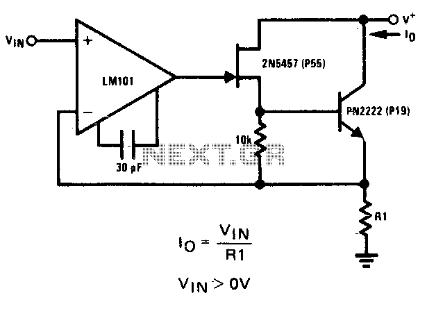
The 2N5457 JFET and PN2222 bipolar transistor exhibit high output impedance. Employing Rl as a current sensing resistor to feedback into the LM101 operational amplifier yields significant loop gain for negative feedback, thereby improving the circuit's capability as a...
Many antique radios operate on batteries, including tube portables like the Zenith model K-401 and "farm" radios used in rural areas without electrical power. This article provides historical context on battery usage in early radios and offers guidance on...
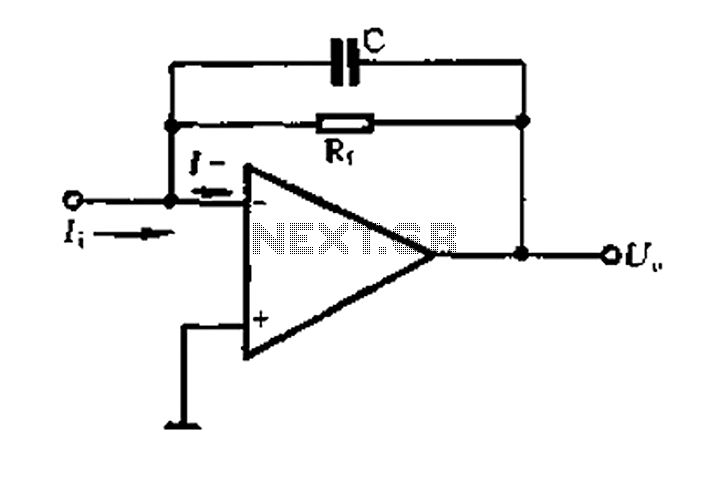
A current-voltage conversion circuit. A current-voltage conversion circuit is designed to transform an input current signal into a corresponding voltage signal. This type of circuit is fundamental in various applications, including sensor interfacing, signal conditioning, and analog-to-digital conversion processes. Typically,...
Continued from the previous post. The same principle is true for the following: temperature to current transmitter. In this case, the input voltage is proportional to the measured temperature, not the rotation. The temperature input is a full analog,...
The amplifier circuit utilizes negative current feedback, which ensures that the load current is primarily influenced by the input signal rather than the loudspeaker's impedance. The inductor current from the loudspeaker generates a voltage across resistor R7, which is...
The current source IC Type LM334 is utilized in this specialized application, which features a minimal temperature coefficient and operates with a very low current draw of only 10 µA at room temperature. This current increases slightly with higher...