
Simple Twi-light using white LEDs

This sunlight-controlled lamp circuit is designed to automatically illuminate LEDs based on ambient light conditions. The core component, the light-dependent resistor (LDR), serves as a sensor that detects the intensity of sunlight. When exposed to light, the LDR's resistance decreases, preventing the transistors T1 and T2 from conducting. This effectively keeps the LEDs off during the day, conserving energy and extending the lifespan of the components.
In contrast, during nighttime or in low-light conditions, the LDR's resistance increases significantly. This change allows the transistors T1 and T2 to enter the conductive state, completing the circuit and enabling the 25 high-brightness white LEDs to illuminate. The use of high-brightness LEDs ensures that the lamp provides adequate light output for various applications, such as garden lighting or decorative illumination.
The circuit design incorporates resistors in series with each row of LEDs to limit the current, thus protecting the LEDs from potential damage due to excessive current flow. Proper selection of resistor values is crucial to maintain the desired brightness while ensuring the longevity of the LEDs.
Assembly of the circuit on a general-purpose PCB facilitates easy integration of components and provides a stable platform for operation. The enclosure should be designed to shield the internal components from environmental factors while allowing sufficient exposure of the LDR to sunlight. The placement of the LDR on the top of the enclosure is critical for optimal performance, ensuring it receives direct sunlight during daytime hours.
Powering the circuit with a 12V battery or adapter provides flexibility in deployment, allowing for both portable and stationary applications. The circuit can be utilized in various settings, including outdoor lighting solutions, where automatic operation based on sunlight is advantageous. Overall, this circuit exemplifies a practical application of basic electronic components to achieve an energy-efficient lighting solution.This sunlight-controlled lamp uses a light-dependent resistor (LDR) as the sunlight sensor and a total of 25 high-brightness white LEDs. Separate resistors are connected in series with each row of the LEDs. The working of the circuit is very simple. During daytime, light falls on the LDR1 and it offers a low resistance. As a result, both the trans istors (T1 and T2) do not conduct and the LEDs (LED1 through LED25) do not glow. On the other hand, during nighttime, the light does not fall on LDR1 and it offers a high resistance. As a result, transistors T1 and T2 conduct and the LEDs (LED1 through LED25) glow. Assemble the circuit on a general-purpose PCB and enclose in a cabinet. Connect the LEDs (LED1 through LED25) and LDR1 on top of the box. Place the unit such that during daytime the sunlight falls directly on LDR1. For powering the circuit, use a 12V battery or any 12V adaptor. 🔗 External reference
Related Circuits

A touch switch circuit schematic utilizing a 555 integrated circuit (IC). When the touch plate is activated, a relay is switched ON for a predetermined duration, which can also be adjusted. The touch switch circuit employs a 555 timer IC...
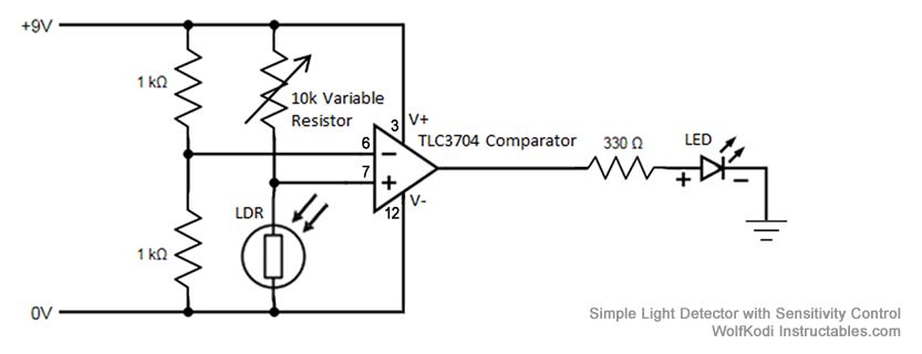
The schematic diagram for the circuit is provided in the accompanying image. As indicated by its name, a comparator is designed to compare two specified voltages. The circuit includes a pair of 1K resistors. A comparator circuit typically utilizes operational...
This metal detector utilizes the CS209A integrated circuit manufactured by Cherry Semiconductor. The CS209A is a bipolar monolithic IC designed for metal detection and proximity sensing applications. It features two on-chip current regulators, an oscillator, low-level feedback circuits, a...
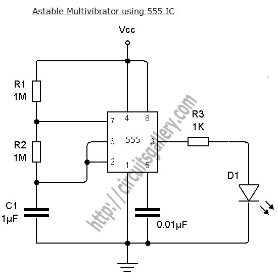
An astable multivibrator can be designed using a 555 timer IC, operational amplifiers, or transistors. The 555 timer IC provides accurate time delays ranging from milliseconds to hours, with the frequency of oscillation adjustable through simple modifications. This is...

This circuit employs a FET as a DC amplifier within a bridge configuration. Resistor R4 is adjusted for meter nulling with switch J1 short-circuited. Any surplus 50-mA meter can be utilized in this circuit. RFC1 represents a suitable RF...

The L293 is designed to provide bidirectional drive currents of up to 1 A at voltages ranging from 4.5 V to 36 V. The L293D variant is capable of delivering bidirectional drive currents of up to 600 mA at...