
switches Wiring a SPDT Relay

A single-pole double-throw (SPDT) switch operates by connecting a common terminal to one of two outputs, allowing for a choice between two different circuits. In this application, the SPDT switch is utilized to control a relay that manages the flow of current to a load. The relay is designed to switch between two states: normally open (NO) when de-energized and connected when energized.
The relay's operation is described in terms of its pin configuration. When the relay coil is energized, pin #2 becomes connected to pin #5, thus completing the circuit to the load. Conversely, when the relay is not energized, there is no connection between these pins, allowing for the load to be disconnected from the power source. This functionality is critical for applications where the load must be isolated when the relay is not activated.
To implement this in a circuit, it is necessary to break the line wire supplying power to the load. Pin #2 of the relay should be connected to the line wire leading to the load, while pin #5 should connect to the load itself. The neutral wire must remain connected directly to pin #5 to ensure proper operation and safety. This configuration allows for the load to be powered only when the relay is engaged, preventing any undesired cycling noise and ensuring the circuit operates as intended.
In summary, the SPDT switch and relay combination provides a reliable means of controlling electrical devices, with specific attention to the pin connections ensuring safe and effective operation within the specified voltage and current ratings. Proper wiring and understanding of the relay's state transitions are essential for achieving the desired functionality in the circuit design.A SPDT switch that simply switches the relay over. Any pointers would be appreciated. When I currently energize the relay, I hear it cycling, which I would image that is not good. I simple want it to "switch" normally on and then when I energize the coil, switch is back. Take a picture of what you have now (i. e. your wired up breadboard). You will get more better/gooder answers that way. Hair_of_the_Dog Mar 7 `13 at 16:15 Yes, but its not right. I guess for now I am looking for pointers on which pins go where. I know its vague, but like I said, I`m struggling a bit. Phil Vallone Mar 7 `13 at 16:16 So that we can explain why it`s right that way and wrong your way. We`re focused on learning rather than end products. Or at least I am. Camil Staps Mar 7 `13 at 16:34 When the relay is energized (power applied) Pin#2 is connected to pin #5. In the unenergized state pin #2 and Pin #5 are not connected -i. e. they are Normally Open (NO). To wire this into a circuit, (it is rated for 1A at 120V AC) you would break the line wire, and connect the relay pins #2 and #5 inline.
Neutral wire will remain connected. in #5 should go to the load, Pin#2 to the source (for safety reasons). 🔗 External reference
Related Circuits
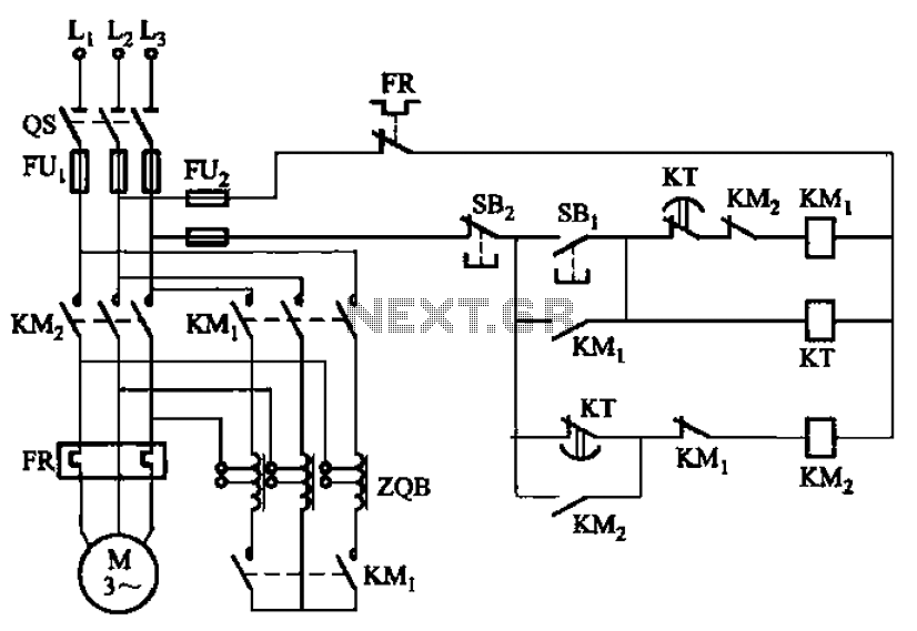
The circuit depicted in Figure 3-49 illustrates an autotransformer that is controlled by a time relay (KT). The delay time set by the KT relay corresponds to the motor's startup duration. The circuit utilizes an autotransformer, which is a type...
A time delay relay is a relay that stays on for a certain amount of time once activated. This time delay relay is made up of a simple adjustable timer circuit which controls the actual relay. The time is...
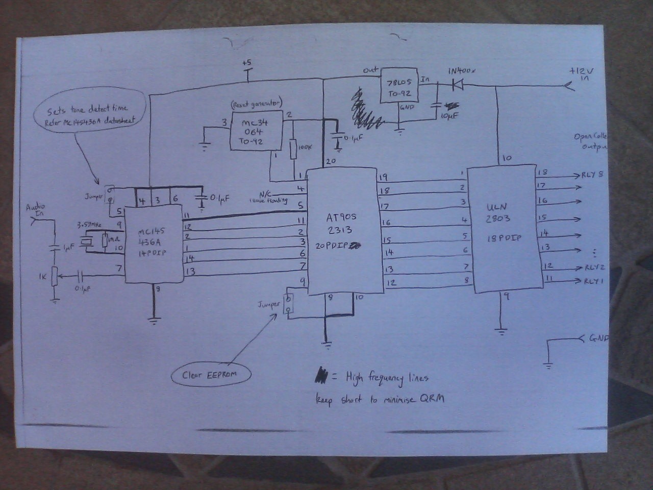
After a power interruption, all relays revert to their previous states, which are stored in non-volatile memory. A Motorola MC145436 DTMF decoder is utilized, clocked by a 3.58 MHz NTSC color burst crystal, providing a divide-by-8 clock output of...

This is an automatic battery charger circuit that utilizes the LM324 integrated circuit, which enhances efficiency. It is capable of charging both 12V and 6V batteries, with filtration managed by switch S1. The circuit is designed to stop charging...
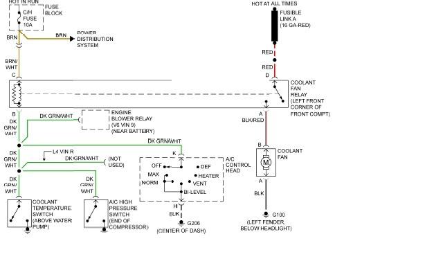
The following page outlines detailed information and the schematic of the 1985 Pontiac Fiero Wiring Diagram and Electrical System. The electrical system consists of: The 1985 Pontiac Fiero features a complex electrical system designed to support various components and functionalities...
This toggle circuit operates by using a couple 555 timers wired as inverters. Pins 2 and 6 are the threshold and trigger inputs to the first timer and pin 5 is the output. The output at pin 5 will...