
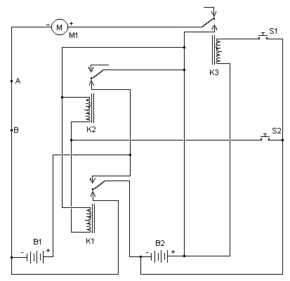
Curtain Control Circuit

The circuit design incorporates a hybrid approach, utilizing discrete components such as transistors alongside integrated circuits (ICs) and relays, enabling both automatic and manual control of curtain movement. The primary function is to automate the opening and closing of curtains via a motorized system, which is linked to a pulley mechanism for smooth operation.
The circuit can be divided into three functional blocks: the bistable latch, the timer, and the reversing circuit. The bistable latch is responsible for maintaining the state of the curtain position, either open or closed, until a change is initiated. This is achieved through the use of flip-flops or similar latch configurations, which can be toggled by the user through switch S3.
The timer circuit introduces a delay feature, allowing the curtains to remain in a certain position for a specified duration before automatically transitioning to the opposite state. This is particularly useful for users who wish to have the curtains open during daylight hours and closed at night without manual intervention.
The reversing circuit is essential for controlling the direction of the motor, enabling it to either retract or extend the curtains. This is typically accomplished using an H-bridge configuration, which allows for bidirectional control of the motor based on the output from the bistable latch and timer.
Switch S3 serves as a mode selector, allowing the user to choose between automatic operation, where the circuit functions based on preset timings, and manual control, where the user can adjust the curtain position as desired. This flexibility enhances the usability of the system, catering to different user preferences and situations.
Overall, this circuit exemplifies a practical application of hybrid electronics in home automation, providing both convenience and functionality in managing window treatments.This hybrid circuit uses a mixture of transistors, an IC and a relay and is used to automatically open or close a pair of curtains. Using switch S3 also allows manual control, allowing for curtains to be left only partially open or closed.
The circuit controls a motor which is attached to a simple pulley mechanism, to move the curtains. I first started this circuit over 20 years ago and apart from now using metal gears, very little has changed. The circuit can be broken down into three main parts; a bistable latch, a timer and a reversing circuit. Toggle switch S3 determines manual or automatic mode. The circuit as shown above is drawn in the automatic position and operation is as follows. The b 🔗 External reference
Related Circuits
The simplest of all motor controllers (besides a straight on/off switch) is the contactor controller. Aaron designed this contactor controller for use in his electric scooter project. It is based around three 12V relays, two 12V batteries, two switches...
Hysteresis in a lamp dimmer or other electrical appliances may cause issues when fine-tuning, leading to a feeling of being out of control. This is a circuit of. Hysteresis in dimmer circuits can lead to undesirable fluctuations in brightness levels,...
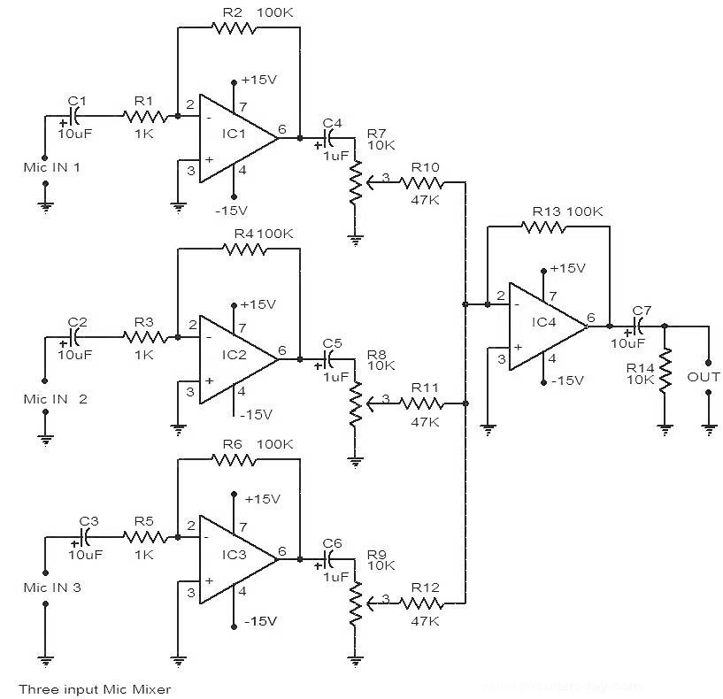
This is a circuit diagram of a 741 IC-based three-input microphone mixer circuit. A total of four 741 ICs are utilized, with IC1, IC2, and IC3 serving specific functions within the design. The circuit utilizes four operational amplifiers from the...
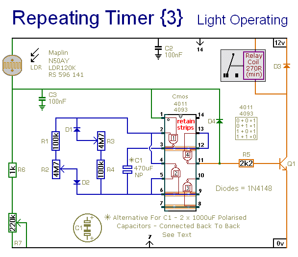
This circuit closely resembles Repeating Timer No. 2. However, the inclusion of a light-dependent resistor (LDR) allows the timer's operation to be confined to daylight hours. Resistor R7 enables the adjustment of the light level at which the timer...
This sound level meter circuit can be used to control the intensity of a sound recording or in a disco. It has 5 measurement domains between 70 and 120 dB. The sound level meter circuit is designed to measure sound...
This project involves a 555 buzzer circuit utilizing the NE555 timer IC, which comes in an 8-pin DIP package and performs a wide variety of functions in electronic circuits. The circuit described will produce a buzzer sound when a...